Good busbar design for enclosures starts where most busbar articles stop: at the sheet metal. We build the cabinets that busbars live in — and the mounting plates, supports, barriers and access openings that decide whether a bar runs cool, stays bolted and can be reached with a torque wrench. Over twelve years of quoting this work we have seen the same failure repeated at three different customers: a bar that was sized correctly for free air, dropped into a sealed box, and quietly running hotter than anyone had calculated. We are careful about boundaries. We cut, form, support, insulate and mechanically assemble busbars, and we read drawings with electrical engineers; we do not certify a switchgear assembly, and the compliance conclusions below belong to whoever signs the declaration.
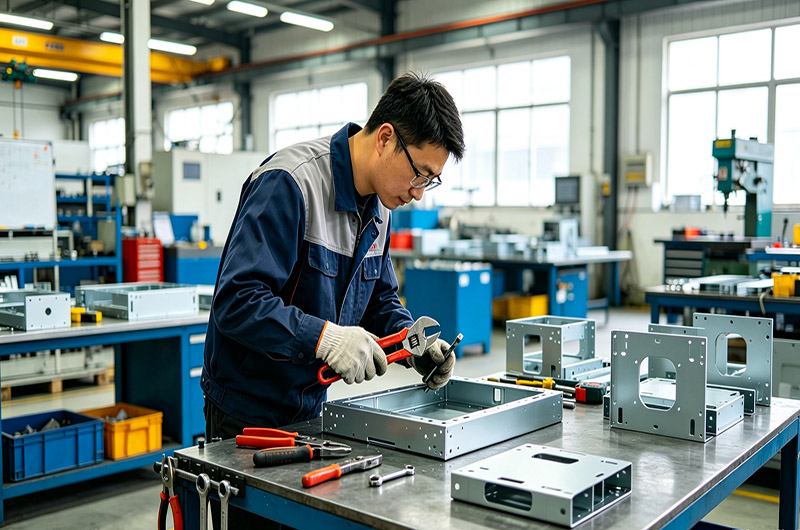
Key takeaways
- A busbar carries three separate duties — continuous current, short-circuit survival, and being the mechanical datum every branch bolts to. Usually only the first one gets calculated.
- The enclosure is a boundary condition, not a container. Internal air temperature, altitude, sealed versus vented construction and solar load move a bar's real current-carrying capacity more than the material choice does.
- Copper wins on cross-section per amp and on joint stability; aluminium wins on weight and material cost, and demands more attention at the joint. Choose on physics, then check the price.
- Sizing is verification, not lookup. A published ampacity table describes a specific test condition; your installation has to reach the same conclusion by test, by comparison with a tested reference design, or by a documented calculation.
- Most busbar failures are joint failures, not bar failures. Contact pressure, surface condition and access for re-torquing decide the service life.
- Short-circuit forces turn the busbar into a structural component. Support spacing dominates the result: deflection under a distributed load scales with the fourth power of span, so halving the span divides deflection by roughly sixteen.
- Half of the decisions — reach through the door, support pitch, barrier geometry, earthing lands, bend access — are made in the sheet metal drawing and are very expensive to change later.
A busbar is a rigid conductor — usually a flat copper or aluminium bar, sometimes a stack of thin laminations — that collects and distributes power at a single node inside a switchgear assembly, a distribution cabinet or a power conversion unit. It replaces a bundle of paralleled cables and does three jobs at once: carry continuous current, survive short-circuit forces, and anchor every branch connection.
Three jobs, three different design drivers
Most of the busbar trouble we get called about comes from treating those three jobs as one.
| Duty | Governing question | What usually fails first |
|---|---|---|
| Carry continuous current | Will the bar reach thermal equilibrium below the permitted temperature rise for its insulation, its joints and the air around it? | Undersized cross-section for an enclosed installation; a joint that creeps and heats further |
| Survive a short circuit | Will the bars, supports and joints hold their geometry long enough for the protective device to clear? | Support pitch too wide; insulator brackets bent; phase spacing lost |
| Provide the mechanical datum | Can every branch connection be made, re-made and re-torqued with the tools a technician actually owns? | A beautiful assembly nobody can service without removing three other subassemblies |
A bar that satisfies the first row and ignores the third is still a warranty claim waiting for its second service visit.
Before anything else: the enclosure is the boundary condition
This is the part that competitors leave out, and it is the part that decides the outcome. A busbar does not live in a laboratory. It lives in a box.
The published ampacity tables circulating online are measured with a bare bar in still air, at a stated ambient, horizontally mounted, on its own. Move that same bar into a sealed IP66 cabinet standing in the sun and you have put a heater inside a thermos. Everything that heat was supposed to dissipate into — air — is now a small fixed volume whose own temperature rises because of your bar and everything else in it.
The thermal budget nobody writes down
When we review a drawing, we ask for four numbers before we ask for the cross-section:
- Expected internal air temperature at full load, not external ambient. Inside a sealed outdoor enclosure, the internal air commonly runs well above the external figure, and the bar is one of the reasons.
- Altitude. Thinner air removes less heat by convection. A bar that is fine at sea level is a different bar on a plateau installation.
- What else is in the box. Inverters, contactors and power supplies already occupy part of that internal budget. If the estimate for a thermal solution exists in isolation, the busbar heat has been double-counted as "someone else's problem".
- Whether the enclosure is sealed or vented. Higher ingress protection generally reduces air exchange, and air exchange is how heat leaves. If the driving spec is ratings rather than airflow, our guides to enclosure ventilation and thermal management cover the trade-off in detail.
This is also why there is no honest single answer to "how many amps does a 60 × 10 bar carry". The answer is: at what internal air temperature, at what altitude, in what orientation, with what surface finish, next to how many other loaded bars, inside what box.
Copper or aluminium: decide on physics, then look at price
Both materials work. Both materials are used in production cabinets daily. The selection logic is cleaner than most of the arguments we hear.
| Property | Copper (Cu-ETP / C11000 family) | Aluminium (1350 / 6101 family) |
|---|---|---|
| Electrical conductivity | ≈ 58 MS/m (the 100 % IACS reference) | ≈ 35 MS/m for 1350; ≈ 33 MS/m for 6101-T61 — take the figure from the mill certificate |
| Cross-section needed for the same current | Baseline | Roughly 1.5–1.65× the copper area for 1350 — more again for 6101 — confirmed against the bar maker's own table at your conditions |
| Density | ≈ 8.9 g/cm³ | ≈ 2.7 g/cm³ |
| Weight for equal current-carrying capacity | Heavier | Lighter |
| Coefficient of thermal expansion | ≈ 17 ppm/K | ≈ 23 ppm/K |
| Behaviour at the joint | Stable, forgiving | Needs more attention — the higher expansion and the oxide film both work against you |
| Typical home | Compact switchgear, dense panel layouts, corrosive sites | Long runs, weight-critical assemblies, cost-driven programmes |
Where aluminium wins
Weight and material cost, mainly. On a large outdoor enclosure where the busbar mass affects transport, lifting hardware and the floor loading of the room it sits in, aluminium can change the mechanical design more than the electrical one. It is also the sane choice for long horizontal runs where the cross-section penalty does not cost you cabinet volume.
Where copper is the only conversation
Three situations push us to argue for copper even when the customer opened with a price target:
- Density constraints. When there genuinely isn't room for a 60 % larger bar plus the clearances around it, the volume saving is real money, not preference.
- Joint reliability over a long service life. Copper's lower coefficient of expansion puts less cyclical strain through a bolted joint across daily load cycles. Over a twenty-year installation that matters more than the day-one material invoice.
- Corrosive or coastal sites. Refer to our write-up on dissimilar metals and galvanic behaviour before you mix metals inside one box.
There is no ampacity row in this table on purpose. Both materials need the verification step in the next section before a current figure means anything.
Sizing a busbar for enclosures is an act of verification, not an act of lookup
Here is the workflow we use when a customer's electrical team asks us what we need in order to build.
- Define the design current honestly — including duty cycle, simultaneous operation of the loads fed from the node, harmonic content if there is significant switching conversion on the bus, and any planned expansion the drawing is supposed to serve.
- Collect every installation condition your source table did not include — internal ambient, altitude, enclosure type, orientation, number of loaded bars per phase, spacing between them, surface finish, solar load if the box is outdoors.
- Pick a starting cross-section from the bar manufacturer's own published conditions — matched to your conditions as closely as their data allows, and recorded with those conditions attached. Ask for the mill certificate and heat traceability on the bar stock; an unverified alloy is an unverified conductivity.
- Close the loop by a recognised verification route for the assembly — verification by test, by comparison with a tested reference design, or by calculation. For low-voltage assemblies those are the three routes IEC 61439-1 sets out for temperature rise. The limits themselves are declared by the original manufacturer against the conditions in that standard — mechanical strength of the conductor, effect on adjacent equipment, permissible temperature of the insulating materials in contact with it, and the contact surface treatment — not a single kelvin figure you can look up for a bare bar. Our UL 508A and IEC 61439 certification guide explains which stakeholder signs which part, and our qualification test plan guide shows how to write down what will actually be measured.
That fourth step is where the discipline is. A number without its verification route is an opinion with units.
The derating inputs people forget to ask about
| Input | Why it moves the answer | Where it should come from |
|---|---|---|
| Internal air temperature | Sets the temperature rise available before you hit the permitted limit for the bar, its insulation and the terminals | Measured, or estimated from the enclosure thermal design — not assumed equal to external ambient |
| Altitude | Less dense air convects less heat away | Site data |
| Number of bars per phase, and their spacing | Loaded bars heat each other; the second bar does not carry double the first | Manufacturer derating data for the exact configuration |
| Orientation | Vertical, edge-mounted bars shed heat differently from flat-mounted ones | Manufacturer data — this one is easy to get wrong by reading the wrong row |
| Surface finish and coatings | Radiative cooling changes with emissivity; sleeving traps heat | Coater and sleeving supplier data |
| Enclosure type | Sealed versus vented changes the whole convective picture | The enclosure specification, cross-checked against the IP/NEMA target |
Each of those rows is a conversation to have in writing, before the first bar is cut.
Skin and proximity: why two thin bars can beat one thick one
Alternating current does not use the whole cross-section uniformly. Skin depth in copper is about 9.2–9.3 mm at 50 Hz and about 8.5 mm at 60 Hz, falling as the inverse square root of frequency. It starts to bite once a bar's half-thickness approaches that figure — so a bar much thicker than roughly 20 mm overall is paying for copper its current is not visiting, and carrying a bending difficulty that serves nobody.
The practical consequence has shaped most of what we build. Two thinner bars stacked with an air gap between them can carry more current than one solid bar of the same total cross-sectional area — more of the copper then sits within a skin depth of a surface — and they do it at the same weight. Against a solid bar of the same current rating, the stack is usually lighter. The saving only materialises if each lamination genuinely shares the current, which puts you straight back into joint design and termination. This is the reason laminated and flexible busbars have taken so much of the work inside battery racks and compact power conversion frames.
The second phenomenon — proximity between adjacent phases — changes the effective resistance and, more importantly for us, sets up the forces in the section below.
Contact surfaces: plating and the aluminium interface
A bare copper surface oxidises. A bare aluminium surface oxidises faster and harder. Neither is a reason for panic and both are reasons for a decision.
| Contact finish | What it buys you | Where we see it specified | Watch-outs |
|---|---|---|---|
| Bare with inhibitor compound | Lowest cost; fine indoors for copper-to-copper | Small distribution boards, dry clean environments | Needs re-application on rework; not a solution for mixed metals |
| Tin plating | Stable contact resistance, good oxidation resistance, the general industrial default | Almost everywhere in industrial switchgear | The joint still needs correct preparation; plating is not a substitute for surface contact pressure |
| Silver plating | Excellent contact behaviour at elevated temperature | High-temperature or high-duty joints | Cost; tarnish handling; specify for the reason or don't specify it |
| Nickel plating | Hard-wearing, higher temperature resistance | Where joints see heat and repeated service | Higher contact resistance than tin or silver — a reason to check the joint design rather than just the finish |
The copper-to-aluminium transition
Putting an aluminium busbar on a copper termination, or bolting either to a dissimilar lug, creates a galvanic couple. Add humidity or a coastal salt atmosphere and the joint is the first thing to degrade. Mitigation is boring and effective: suitable plating or transition interface material, exclusion of moisture at the joint, and a drawing note naming every metal present so nobody has to guess where the galvanic chain starts. Our material selection guide covers the substrate side of the same conversation.
Joints: where busbar reliability is actually made
Every experienced panel builder will tell you the same thing, usually after a hot-joint investigation: the bar almost never fails, the joint does.
Joint resistance is governed by four things that are all in someone's control at build time — the real contact area, the contact pressure, the condition of the surfaces (oxide, plating, compound, contamination), and whether that pressure survives years of thermal cycling. Note that "real contact area" is far smaller than it looks: two apparently flat surfaces touch on their asperities, which is precisely why pressure matters so much and why a correctly specified spring element earns its keep in an assembly that will see daily load cycles.
Torque is a process, not a single number
We deliberately do not publish torque figures here. The reason is practical: the correct value depends on the fastener, its coating, the spring element in the stack, the bar surface, and the manufacturer's own tested data for that combination. Publishing one number invites someone to apply it where it does not belong.
What belongs on the drawing instead is a sequence and a verification: which brands and grades of fastener and spring elements are approved, what order the fixings are brought up in, how many passes, at what fraction of the final value, and what check confirms the result. A routine joint-resistance check, or simply re-torquing after the first full thermal cycle, catches more future faults than any tightening specification alone.
Service access — the sheet metal contribution
This is squarely our problem and it is routinely discovered too late. Ask these before the first article is made:
- Can a torque wrench reach every joint through the intended access opening, with the cables dressed?
- Does anything have to come out to service one joint — and does the maintenance document know that?
- Is there room in front of the joint for the tool head and the technician's hands, or only for the bar?
- Do the supports take the reaction load of a service technician leaning on the bar with a wrench?
We have rebuilt plenty of assemblies for the want of a forty-millimetre difference in a cut-out position. Our piece on access, doors and covers covers this in more detail, and it is cheap reading compared with a second tooling programme.
Joint defects we actually see
| Symptom | Usual cause | What fixes it |
|---|---|---|
| Local discolouration around one bolt | Insufficient contact pressure at that point, or contamination on the interface | Restore surface, correct the stack-up, re-make the joint in sequence |
| Joint heats up progressively over months | Load cycling relaxing the fastening; no spring element in the stack | Correct the stack-up design, not just to re-tighten this unit |
| Uniform dulling across the whole bar | Normal surface ageing | Usually acceptable; confirm with your own acceptance criteria, not ours |
| Green or white deposits at a transition joint | Galvanic action across dissimilar metals with moisture present | Correct the interface design and seal the joint environment |
| Arcing trace between a bar and a support | Tracking path, contamination, or insufficient clearance for the pollution degree | Review the clearance/creepage design, the comparative tracking index (CTI) of the support material measured per IEC 60112, and the cleaning regime |
Short circuit: the busbar becomes a structural problem
The moment a fault occurs, conductors carrying current in opposite directions repel each other very hard. For two parallel conductors the force per unit length follows directly from basic electromagnetism:
F/L = μ₀ · i₁ · i₂ / (2π · d) ≈ 2 × 10⁻⁷ · i₁ · i₂ / d newtons per metre
where the currents are instantaneous values and d is the centre distance between conductors, in metres. Set against the prospective fault current your protection is actually going to let through for however many cycles it takes to clear, this is why "approximately" values in a support design are not acceptable.
Two implications follow, and both change the metalwork:
- Support pitch dominates. For a single simply supported span under a uniformly distributed load, deflection scales with the fourth power of the span — halve the pitch and you divide deflection by roughly sixteen. Real busbar runs are usually continuous over several supports, so treat that as the direction of the effect, not the number: IEC 60865-1 is the recognised method for calculating electromagnetic effects on rigid conductors, and it works from the peak short-circuit current rather than the rms symmetrical value. We build to the result; the calculation belongs to the assembly's designer.
- The insulator bracket carries the load, not the bar. The support has to transmit the fault force into the panel structure without creeping, cracking or losing the phase spacing that your clearance design depends on — the same load path our arc-resistant switchgear fabrication guide treats at the assembly level.
Busbar support insulators
Support material selection is an electrical and mechanical decision together: the comparative tracking index has to suit the pollution degree and the creepage path you designed, and the mechanical strength has to survive the peak force above. Common choices include glass-reinforced thermoset polyester mouldings, engineering thermoplastics such as PBT, and ceramic bodies where temperature or tracking requirements drive you there. Each has a different story on moisture absorption, creep and brittle failure. The interface between support pitch and required creepage distance is exactly where our clearance and creepage guide picks up the thread, because the shortest route between two phases often runs along the surface of the very part holding them apart.
Remember the earthing side too: our grounding and bonding design guide explains why the protective earth path through a painted structure needs the same attention as the phase conductors.
Building it into the sheet metal box
Here is the order of operations we would expect on a job where all parties are doing their job:
- Freeze the busbar drawing with the enclosure drawing. They are one interface, not two documents that should agree later. Any change to either should trigger the change-control process in our drawing revision and ECN guide — bolted hole patterns are the single most expensive thing to re-cut.
- Machine the bar set — cut, punch or drill, then form to the specified bend radii. Copper work hardens differently from steel and its bend behaviour needs its own rules; if you are used to bending sheet, do not carry those radii across unchanged. Tight multi-hole patterns are also where dedicated tooling and fixtures start to earn their money.
- Deburr and clean, then plate. Burrs at joint interfaces are the cheapest known way to build future heat into a joint, and plating is the one step where what a coated surface can and cannot be asked to do has to be agreed before the bar is cut.
- Fit supports and barriers into the enclosure, verifying that clearances hold with the bar actually installed — not on the model alone.
- Install bars, observing the joint sequence, then torque in passes.
- Verify to the extent the drawing assigns to us — visual, dimensional and joint resistance as specified, and dielectric only where the specification places that test in our scope. We record everything against the serial number, and our quality control and inspection guide has a template that transfers well to busbar records. The assembly-level temperature-rise and short-circuit verifications belong to whoever signs the declaration — what we supply is the evidence they point at.
- Label and photograph. The photograph is the cheapest diagnostic you will ever own.
The tolerance conversation
A busbar hole pattern, an insulator bracket position and a mounting plate feature form a stack. Individually each is comfortable. Accumulated across an assembly with several supports in a row, the last bracket can end up fighting the bar. This is the ordinary stack-up problem described in our tolerance guide, applied to something that carries hundreds of amps. The fix is rarely a tighter tolerance everywhere — it is usually one deliberately generous slot at one end of the run, and a support design that does not depend on the bar being in exactly one position.
What to ask for in a verification report
When you receive a busbar assembly, the paperwork should tell you what was actually established and by which route — the same principle as a first-article inspection record applied to the first bar set.
| Item | What the evidence should establish | Typical evidence |
|---|---|---|
| Current-carrying / temperature rise | Temperature rise limits met under defined load and ambient conditions | Test report at stated conditions, or documented comparison to a tested reference design, or a documented calculation |
| Short-circuit withstand | Bars, joints and supports retained geometry and function | Type test report, or calculation based on a recognised method with the inputs shown |
| Clearances and creepage | Measured distances met the design values for declared pollution degree and overvoltage category | Dimensional inspection record with a drawing callout |
| Dielectric | Insulation held at the specified test voltage | Test record with test voltage and duration |
| Joint integrity | Serialised record of joint preparation, sequence and verification | Build record with sign-off and photographic reference |
A report that gives a conclusion without stating the conditions is not a report; it is a receipt.
Six product lines, six busbar realities
Six product lines, six different reasons a busbar gets specified wrong.
| Product line | What the busbar is doing | What tends to hurt |
|---|---|---|
| EV charging piles | High-current DC distribution inside a sealed, publicly accessible plinth | Internal air temperature in a sealed box; service access through restricted openings |
| Energy storage cabinets | Rack-level collection into a single node, usually in a very dense arrangement | Space is so tight every support decision is a compromise; see our energy storage enclosure guide |
| Distribution and control panels | The classic role — the node every branch bolts to | Nobody made room for the torque wrench; see our control panel enclosure guide |
| Telecom and network | Large currents at low voltage, with a very long unattended service interval | Joints that nobody is going to re-torque for a decade; see our telecom enclosure guide |
| Industrial HMI frames | Usually low power — but often the display supply shares space with signal wiring | Separation discipline rather than cross-section |
| Outdoor municipal | Mixed loads in a weather-exposed box, often with long service intervals | Moisture at joints and supports; our outdoor IP guide covers the box side |
Three jobs from our own log
A medium-sized Italian panel builder, 2022. They had a sealed cabinet with an aluminium busbar running at what sea-level, open-air conditions would have called comfortable. It ran hot in southern European summer installations, and the symptom arrived as nuisance tripping rather than as visible damage. The eventual fix was not a bigger bar: it was a documented enclosure ventilation change, a modest section increase, and for the first time a stated internal air temperature on their own drawing. We are quoting them still.
A US energy storage integrator, 2024. Space inside the rack cabinet was so contested that the mechanical design wanted 40 % of the busbar volume back. The answer was a laminated stack with a defined spacing between laminations and supports on a much tighter pitch. It cost more per unit and less per kilowatt.
A telecom cabinet programme, 2021. Low voltage, high current, thirty sites in a humid coastal region, nobody going back for years. Almost every euro went into joint preparation, plating and the interface details, and almost nothing into extra copper. As far as our own service log shows, we have not had a joint complaint from that programme.
We describe these as our own observations, with their conditions attached — not as industry statistics.
Twelve-point busbar DFM checklist
This is the busbar design for enclosures checklist we run before a bar is cut:
- Write the internal air temperature on the drawing, not just the external ambient.
- State whether the bar runs vertically, horizontally or edge-mounted — and do not let the assembly technician decide.
- Put every derating input in the RFQ package so nobody is quoting a different installation.
- Choose the contact finish deliberately, and name it on the bar drawing.
- Avoid mixing metals inside one joint without a documented interface treatment.
- Keep the number of joints down. Every joint is a future investigation.
- Design the support pitch from the prospective fault current, then check the creepage path that results.
- Give the torque sequence a home on the drawing, including service re-check.
- Check tool clearance at every joint with the cables dressed, before the first article.
- Leave at least one generous slot in each long run to absorb stack-up.
- Sleeve or barrier only after considering what sleeving does to heat rejection.
- Photograph the assembly before anything is closed up.
What to send us with your busbar enquiry
For each busbar set: material and alloy; cross-section; length and developed shape; number of bars per phase and their spacing; support pitch and insulator type; contact finish per face; every hole position and diameter with tolerances; any sleeving or barrier requirement; the target assembly environment including internal air temperature and altitude; the access envelope a service technician will actually have; and whether you need the joint sequence and verification documented at unit level. If you would rather skip the list, our RFQ checklist collects most of it, and our lead time guide explains what happens next.
Frequently Asked Questions
Does SanJun certify the electrical assembly or take responsibility for compliance?
No, and you should be wary of any fabricator that says otherwise. We fabricate the enclosure and build the busbar set mechanically to your drawing — cutting, forming, plating coordination, supports, barriers, assembly and records. The electrical verification of the completed assembly belongs to the panel builder or manufacturer putting the declaration of conformity on it. What we do is make every part we control verifiable: serialised build records, joint preparation evidence, measured clearances and photographs, so that whoever signs has something to point at.
How many amps can a 60 x 10 mm copper busbar carry?
It depends on the installation, not on the bar size alone. There is no responsible single answer, and any article that gives you one without stating conditions is doing you a disservice. The current a bar carries depends on its material and temper, surface finish, orientation, the number of loaded bars per phase and their spacing, the internal air temperature around it, the altitude, and whether the enclosure is sealed or vented. Take the starting value from the bar manufacturer's published conditions, then reduce it by the derating inputs for your actual installation, and close the loop with a recognised verification route for the assembly.
Why does my busbar run hotter inside the cabinet than the calculation predicted?
The internal air temperature assumption, in almost every case we have investigated. If the calculation used external ambient because nobody wrote down an internal figure, the bar has no headroom left — it is heating the same limited volume of air it was supposed to be dumping its heat into. Sealed enclosures, sunlit outdoor installations and high-altitude sites are where this shows up first. Measure or estimate internal air temperature at full load, put it on the drawing, and re-check the input next to it — the number of other heat sources sharing that same volume.
When should I choose aluminium busbar over copper?
Choose aluminium when weight and material cost dominate and you have the volume for a larger cross-section — long runs, weight-critical assemblies, cost-driven programmes. Stay with copper when space is genuinely contested, when the joint will see many years of daily load cycling, or when the installation is coastal or corrosive. Aluminium's greater thermal expansion and its oxide film make the joint design more demanding, so if the programme cannot carry that attention, copper is usually the cheaper decision over the life of the installation.
How do I stop busbar joints from loosening over time?
Treat the joint as a designed stack, not a bolt. Specify the fastener and the spring element together, keep the mating surfaces clean and correctly finished, tighten in a defined sequence and in stages rather than in one pass, and verify the result — a joint resistance check or a re-check after the first full thermal cycle catches far more than re-tightening alone. Also make sure a technician can actually reach the joint later; a joint nobody can reach with a torque wrench is a joint nobody will ever re-check.
How much does support spacing matter for short-circuit performance?
Enormously, because deflection under a distributed load scales with the fourth power of the span. Halving the support pitch divides deflection by roughly sixteen, and the support is what transmits the fault force into the panel structure. It is the cheapest structural intervention available, and it should be derived from the prospective fault current your protection actually lets through — not copied from a previous design because the drawings looked similar. Check afterwards that the resulting pitch still leaves the creepage path your pollution degree requires.
Can I take a busbar design from one enclosure programme and reuse it in another?
Only the parts that are independent of the box. The cross-section, plating and joint design may transfer if the electrical conditions are genuinely the same, but anything involving support pitch, clearance to the structure, access through openings, internal air temperature and therefore the derating inputs has to be re-derived. This is also why a busbar set is so expensive to change once cut — see our guide to drawing revisions and ECN before you freeze either drawing.