Nobody calls about a weld that broke. They call because a door stopped closing. In 2019 an Italian panel builder photographed a 1.8 m control cabinet: after fourteen months the latch-side corner had dropped, the gasket lost contact across the top third, and condensate tracked down the inside of the door onto a drive. The hinges were intact; nothing was abused. The panel simply was not stiff enough to hold itself flat against its own gasket — a decision made on the drawing. Electrical enclosure door design is usually the last thing a project decides and the first thing that fails in service. This guide covers the six architectures, the frequency that picks between them, sag, sealing, bonding and RFQ wording.
Enclosure Door Design Decides How Your Cabinet Ages
- The door is the only moving part in a static box, so the only part that wears.
- Five jobs at once: sealing, impact protection, bonding, shielding and human interface.
- At least 90° of clear opening — from an installation rule, not a door standard.
- One latch cannot hold a perimeter; between points it leaks.
- Hinges are not a bonding path: strap plus a stud each side.
- Twelve RFQ fields separate a real door from a flat plate with holes.
Why enclosure door design carries more risk than any other part
Everything else is designed once and stays put. The door is a mechanism, a gasket flange, a guard, an equipment mount and an operator interface on one surface, doing all five jobs after thousands of cycles in the weather.
Why enclosure door design is decided too late
In quoting calls a door gets one line: "hinged, left-hand, with a lock." That becomes metal using whatever hardware is cheapest, unchecked against what hangs on the leaf — and later has to be shimmed shut. Architecture, load path and point spacing are cheap before the frame is nested, expensive after.
Five jobs, one joint
Each pulls a different way: sealing wants a soft evenly compressed gasket, impact resistance a stiff heavy panel, bonding bare protected contact metal, shielding high pressure at short intervals, and the operator gloved hands with no tools. Most door problems are one of those five losing an argument with another. Set grade targets first — see NEMA vs IP enclosure ratings — then design metal to hit them.
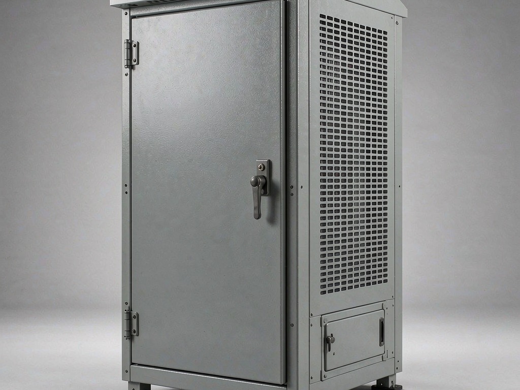
Six door, cover and access architectures
Access frequency and surrounding space choose among these six, not taste.
Hinged doors
The default, because a single leaf carries mounted equipment best and stays attached to the cabinet. The catalogue half of that decision is in our hinge and latch hardware selection guide.
Quick-release covers
Quarter-turns, captive screws and clips turn twenty fasteners into two seconds — right for filter boxes and small chambers. The weakness is geometric: each fastener compresses locally, so on a larger face midspans lift and the seal is a suggestion. Above a modest square, quick release has to become a linked multi-point system.
Lift-off doors
Full-width opening with no swing, which suits a skid, a container or an 800 mm aisle. The cost is procedural: headroom, a support feature, a disconnection order and a locating pin so reassembly repeats.
Sliding doors
They eliminate the opening envelope entirely, which is why they appear on operator desks and machine-integrated panels. They are the hardest to seal: the panel must be pressed normal to its gasket while sliding parallel to it. Specify them where space genuinely binds.
Door-in-door and inner doors
Two access tiers: operators use the inner panel every shift, technicians open the outer leaf occasionally. The constraint is depth consumed between skins — usable inner depths in mainstream catalogue ranges run in the tens of millimetres. Display mounting follows our HMI door mounting rules.
Fully bolted removable panels
Cheapest option and often the right one: no swing, no hinges bought, genuinely flat and stiff. It needs tools and somewhere to put the screws, and behaves like a fixed guard — see below. Use it for rare planned access.
Choosing between the six
Scores are relative, 5 best. Access speed includes tooling time.
| Architecture | Sealing | Access speed | Cost | Typical application |
|---|---|---|---|---|
| Single-leaf hinged door | 5 | 5 | 3 | Control, power, telecom, outdoor cabinets |
| Lift-off removable door | 5 | 2 | 3 | Wide openings in skids, containers, tight aisles |
| Quick-release cover | 3 | 4 | 2 | Filter boxes, small chambers |
| Sliding door | 2 | 3 | 4 | Operator desks, machine panels, dry locations |
| Door-in-door / inner door | 4 | 4 | 4 | Daily use inside, occasional access behind |
| Bolted removable panel | 2 | 1 | 1 | Rare planned access, transport panels |
The largest leaves we build pass two metres and carry cooling hardware too; see our energy storage cabinet guide for what changes at that scale.
Access frequency: the decision most teams get backwards
Teams pick a door from habit and later discover the maintenance pattern does not match it. Work the other way: how often is each opening used, and for how long?
Build the access frequency matrix
Every opening needs a row. "Operator" means gloved hands.
| Frequency | Dwell | Recommended architecture | What goes wrong otherwise |
|---|---|---|---|
| Several per shift | Under a minute | Hinged door, tool-free quarter-turn or linked points | Tool-required doors get propped open |
| Daily to weekly | 2–10 min | Hinged door, points added once size defeats one latch | Every opening costs floor space |
| Monthly to quarterly | 10–60 min | Lift-off or hinged, locating features, captive fasteners | Panels refitted with half their screws |
| Yearly, planned | Over an hour | Quick-release cover or bolted panel, retained fasteners | Nothing bad; spend on sealing |
| Commissioning only | Once | Panel with no intended future access | You paid for access nobody will use |
We learned this the expensive way on a German battery storage skid in 2022: six faces, each with roughly thirty screws because that was cheapest, inspected quarterly. By the second visit panels came back with a random subset of screws and uneven gasket lines. Nothing was mechanically wrong — it was a mismatch between architecture and frequency. All six became lift-off doors on locating pins with two captive quarter-turns; one technician now does the round alone.
What guarding standards imply
EN ISO 14120 draws a line enclosure teams rarely use deliberately: fixed guards need a tool to remove, movable guards open without tools and are normally interlocked. The consequence is predictable — enter a face every shift and someone defeats a fixed guard within a month. So no bolted panel for a daily task, no interlocked hinged door for an annual one.
When the door can reach live parts
What does opening it expose? Where a door or cover can bring someone within reach of live parts, current UL 508A practice recognises three approaches — key or tool, interlock with a disconnecting means, or live parts protected inside. Real panels mix them, and marking duties follow — see our nameplate and warning marking guide. Note the boundary: it governs reaching live parts safely, not your architecture.
Door sag and panel distortion: mechanics and fixes
A door is a plate loaded in its own plane by gravity and out of it by gasket and latches. Every sag story has the same shape: the panel bends, geometry drifts, the seal opens somewhere.
Where sag actually comes from
The leaf's weight plus anything on it — HMI, filter fans, transformers — matters most when the mass sits away from the hinge axis, where it creates a moment. Add continuous gasket closing load plus vibration, and relaxation is progressive rather than one-time. That is why growing door-mounted mass belongs with our vibration and shock testing guide.
Stiffening without paying the weight penalty
Thickening works and taxes every opening forever. Forming usually wins: stiffness rises with the square of how far material sits from the neutral axis, so moving material out of the panel plane beats piling it up in the plane.
| Method | What it adds | Weight cost | Stiffness gain | Process risk | Not worth it when |
|---|---|---|---|---|---|
| Return flange | Mounting land, edge stiffness | Very low | Baseline | Low; check flatness | Rarely enough |
| Hemmed / closed perimeter edge | Closed tube around the border | Low | High | No piercing after hemming | Light doors, cosmetics dominate |
| Formed ribs in the skin | Stiffness between keepers | Almost none | Medium–high | Ribs conflict with flat lands | Thin skins |
| Welded frame or hat sections | Highest stiffness; carries mounted load | High | Highest | Distortion, sequenced welding | Small light doors where finish wins |
Real multiples depend on section and boundary conditions, so verify on your own door. Material matters too: solving stiffness by changing gauge costs more than forming, shifts the galvanic picture and moves the declared carbon — see our material selection guide, our stiffener and rib design guide and what low-carbon steel actually changes.
Hinge count, spacing and load sharing
There is no universal count or spacing rule for enclosure hinges; anyone quoting one is quoting a house practice. But fewer points and wider spacing means more load each and more free edge to droop, so tall, heavy or loaded leaves want continuous hinges or closely spaced ones biased towards the loaded end. Two figures of merit hold almost everywhere: enough flat land behind hinge screws for the fastener to work in shear rather than peel (common practice around 8–12 mm), and hinge holes far enough from a bend line that forming does not distort them — the floor we work to is twice material thickness plus the inside bend radius, which on 2 mm sheet is nearer 6 mm than the 3 mm you get from 1.5 × thickness. Size both against a number rather than a habit: door mass plus everything mounted on it, multiplied by the distance from the hinge axis to their combined centre of gravity, divided by the number of hinge points — then check that against the maker's radial and axial rating. Fastener pull-out and peel loads are in our fastener selection guide.
Tolerance stack-up and weld distortion
More doors are scrapped for geometry than strength: frame racking, non-coaxial bores, holes punched from an edge, coating on mating fits. Trivial alone, binding together. Fix them on the drawing: one datum per part, stated diagonal tolerance and bore coaxiality, symmetric weld sequence, threads and bonding lands masked or plugged before coating. Detail in our stack-up guide.
Opening envelope, sweep path and service clearance
Drawings show the cabinet. They rarely show the open door, which is where installations go wrong.
Envelope is not sweep path
The envelope is what the leaf and everything on it sweeps — handle, pocket, door-mounted HMI. It decides whether another cabinet fits beside this one. The sweep path is the trajectory of everything crossing the joint — strap, harness, sometimes a braid longer than anyone expected. It decides strap length and what chafes. Some catalogue ranges quote angles well past 180°: fine on a drawing, a problem in a row.
The 90° floor — and what it does not say
The number everyone quotes comes from OSHA's working-space rule, 29 CFR 1910.303: within the voltage range it covers, space in front of equipment must allow doors or hinged panels to open at least 90°, its width being equipment width or 762 mm (30 in), whichever is greater — conditions above 600 V are treated separately. Read it precisely, because it is misquoted constantly: 762 mm is the width of the clear space in front of the equipment, not the swing radius of your door, and 90° is a floor for that space rather than a specification for the hinge you buy. This is installation working space. It is not a door design standard, says nothing about thickness, hinge count or latch type, and does not transfer to internal electrical distances, which our clearance and creepage guide covers. Confirm the edition and interpretation with the authority having jurisdiction.
What rides on the door: HMI, harness, bonding strap
Anything on the leaf adds weight at a lever arm — back to the mechanics above — plus something crossing the joint that must survive the hinge cycle count. Three rules hold almost universally: cross the joint close to the hinge axis, specify conductors rated for continuous flexing, and keep everything clear of the latch. A recessed 15-inch panel plus its supply is enough to change your hinge decision; see the HMI door mounting guide.
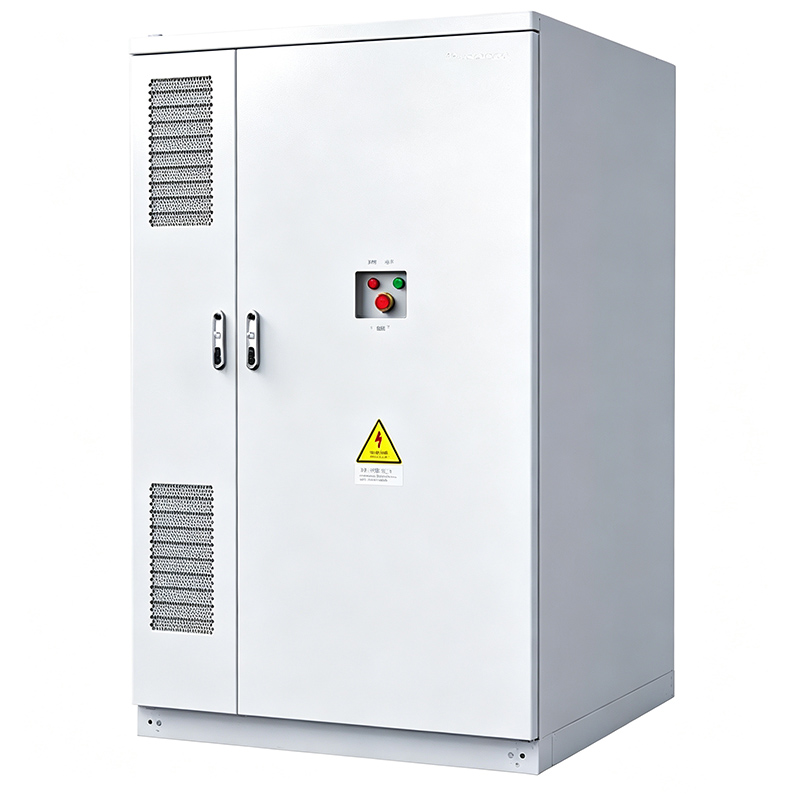
Sealing: multi-point latching and compression uniformity
Most reports saying "the seal failed" mean "the seal was never uniformly compressed". Point layout decides what the gasket can do.
Why one latch cannot hold a perimeter
A gasket needs roughly equal compression all the way round. One latch applies a point load, the panel is a spring, and load decays between points — worst at the far corner. On a small cover that survives; on a metre-tall leaf it guarantees a leak path. Material and compression set belong to our gasket compression and IP sealing guide.
The load path of a multi-point system
Handle torque enters a linkage or rod set, converts to normal force at each keeper, compresses the gasket, which pushes back and deflects the panel — and that deflection is what starves the zones between keepers, so point density attacks the real problem. No spacing is standard-mandated; shielding work commonly uses contact intervals around 150–300 mm, a useful order of magnitude, but your answer depends on stiffness and deflection budget.
Reading the gasket imprint
The cheapest diagnostic there is — pressure-sensitive film or feeler gauges. Open the door, inspect witness all the way round.
| Symptom | Mechanism | How to read it | Fix at design or assembly |
|---|---|---|---|
| Hard imprint hinge side, light free edge | Leaf pivots about the hinge line | Compare imprint width hinge side vs free edge | Move a keeper nearer the hinge; shim the hinge leaf |
| Imprint tapers at corners | Mid-height latching bows the panel | Look for taper in the corner imprint | Add top and bottom points |
| Wet track below the bottom | Lowest compression meets gravity | Compare joint height with the frame sill | Drip geometry; seal line above standing water |
| Fine when new, gone after one summer | Compression set in polymer and metal | Re-imprint after cycling to service temperature | Specify compression-set data; keep take-up travel |
Double doors and the centre stile
Double leaves buy width and two problems: both leaves must close on one datum plane, and the centre stile — least supported member — carries compression both ways. Give each leaf a positive stop against the same reference, give the stile gasket its own compression path, and run ingress checks with both leaves closed together.
Door stiffness, IK impact and EMC continuity
Stiffness is not free. Every plateau you add for one requirement taxes another, which is where door arguments start.
The largest, least supported surface
Under impact the door is nearly always the weakest face: biggest unsupported area, least predictable backing at the hinge. IK levels are defined in IEC 62262: take the energy values from the current edition rather than from memory, since misquoted joule figures are the commonest error here — as a scale check, IK08 is 5 J, IK09 is 10 J and IK10 is 20 J. Two points matter more: stiffening under the likely impact point turns a dent into a buckle, and the fastener often fails first. Our IK impact rating guide covers selecting the level.
The seam sets the shielding ceiling
The door seam is nearly always the weakest link in a shielded enclosure: it is the only long continuous slot in an otherwise closed box, so it behaves like an aperture whatever the wall looks like on paper. What makes it work is pressure at short intervals, bare conductive lands, and galvanic compatibility with the base metal. Practice beyond the joint sits in our EMI shielding continuity guide.
The trade-off nobody writes down
Stiffening raises impact resistance and adds weight, and weight increases sag. Highly conductive elastomer seals easily but takes compression set faster. Protective finishes often insulate the surfaces you need conducting. There is only a sequence: fix architecture and frequency, size stiffness, set point density, then choose gasket and finish.
Grounding and bonding across the moving joint
Why the hinge is not a bonding path
A hinge is a bearing: it has clearance, gets lubricated or seizes, is coated, and frets every time the door moves, so impedance drifts unpredictably. We had a coastal EV charging cabinet in the United States where the reading taken across the hinge depended on whether the door had been opened recently. Mysterious until you accept that a hinge is a mechanical device first.
The industry answer is boring and reliable: a bonding strap, plus a stud each side of the joint. Mainstream North American catalogue cabinets commonly carry one stud on the door and one inside the body, a pair per leaf, because nobody trusts the hinge. Sizing, length limits and finishes sit in our grounding and bonding design guide, and the loop length the strap has to survive is derived in our cable management guide.
Strap type, length and routing
Braided strap beats a round conductor at high frequency: a flat wide section has lower inductance. Leave slack for the full opening angle, route it so the slack never binds, and anchor outside the sweep path. In any strip-down it comes off first and goes back on last, so keep it reachable.
Twelve door failure modes and their design root causes
Everything above compresses into a table for drawing review and pre-shipment checks.
| Symptom | Mechanism | Root cause | Countermeasure |
|---|---|---|---|
| Latch-side corner drops | Panel cannot carry the moment from weight and mounted load | Few points, wide spacing, no stiffening | Closer spacing at the loaded edge; formed returns; adjustable keepers |
| Door binds closing | Accumulated tolerance: non-coaxial hinges, racked frame, twisted leaf | No stated datum, diagonal or coaxiality | One datum per part; fixtured frames; adjustable hardware |
| Leak at the bottom | Lowest compression meets gravity | No point low on the tall edge; no compression target | Low keeper; keep joint above the frame sill |
| Heavy hinge side, light free edge | Leaf pivots about the hinge line | First keeper too far from the hinge line | Re-space keepers; lower closing force |
| Hinge screws strip | Fasteners loaded in peel against thin sheet | No backing plate or pull-out requirement | Backer plates or clinch nuts; specify pull-out load |
| Bonding strap frays | Flexing below minimum bend radius each cycle | Strap routed across the swing | Anchors outside the sweep; slack at full opening |
| EMC varies unit to unit | Seam impedance tracks paint, torque, flatness | Painted faces; no torque callout | Masked bare lands on the drawing; state torque |
| Continuity lost after coating | Film on bonding surfaces | No masking callout in the finish note | Masking on the drawing; plugged threads |
| HMI harness chafes | Loop too short; sharp cutout edges | Loop length not derived from hinge geometry | Cross near the hinge axis; radius edges |
| Latch misses after coating | Film thickness consumes fit clearance | No coating allowance at mating interfaces | Allow for finish; pluggable threads |
| Centre stile weeps | Two leaves closing on two planes | No common stop; stile seal relies on leaf pressure | One datum for both leaves; independent stile compression |
| Contact decays after heat | Compression set in polymer, permanent set in metal | Gasket specified by profile, not performance | Specify compression-set data; keep take-up travel |
Verify in the same order: hang the specified load, gauge bores, imprint the perimeter, cycle the strap, measure seam impedance — evidence for an enclosure qualification test plan. With a drawing open, start cheaper: pick three failures you have had, then find what your drawing says about them.
DFM checklist for doors, covers and access panels
What we run internally before a door folder reaches the shop, on top of general sheet metal DFM fundamentals.
- Dimension hinge and latch holes from one datum, never a bend.
- State hole-to-bend distance with tolerance, not shop folklore.
- Leave land behind each hinge screw; common practice around 8–12 mm, sized to real load.
- Put frame diagonal tolerance and hinge bore coaxiality on the drawing.
- Sequence frame welds symmetrically outwards.
- Mark masking and plugging locations.
- Specify adjustable keepers so stack-up is tuned, not shimmed.
- Form before thickening: a hem buys more stiffness per gram.
- Keep one keeper near the hinge line and one low on the tall side.
- Route the strap outside the sweep path; slack at full opening.
- Check the envelope against neighbours, then the sweep path.
- Stop both leaves on one datum; give the stile its own compression path.
- Leave glove clearance around handles and behind the escutcheon.
- Make every removable panel a one-person job: pin, support, rest point.
- Threaded inserts, not rivets, at hardware positions.
- Ask for first-article photos: imprint, diagonals, continuity.
How to write the door spec in your RFQ
None of this helps if it never reaches the person quoting. In enclosure door design, the RFQ section is where decisions become requirements or quietly become the supplier's choice.
The twelve fields a door spec must contain
| Field | Why the supplier needs it | Typical wording | If you leave it out |
|---|---|---|---|
| Architecture | Sets tooling and cost | "Single-leaf hinged door, left-hand, multi-point latch" | Cheapest hardware wins |
| Size, material, thickness | Everything downstream depends on it | "1800 × 800 mm, 2.0 mm CRS, powder coated" | Thickness becomes a bid variable |
| Opening angle, envelope | Eliminates options before costing | "Open 180° with 250 mm clear in front" | Hindsight, then a spacer |
| Door-mounted load | Drives hinge count, stiffness, strap size | "22 kg including HMI, CoG 180 mm from hinge axis" | Sag in month three |
| Hardware type, count, spacing | Directly inspectable | "Continuous hinge; multi-point latch, adjustable keepers" | All adjustment leaves the quote |
| Service life in cycles | Selects bearing class | "10,000 cycles before adjustment is needed" | Consumer hardware in a plant |
| Ingress target and verification | Turns a claim into evidence | "Verified as installed; report required" | Rating belongs to a brochure |
| Gasket material, section, target | Sets closing force and life | "Per supplier force data; verified by imprint" | Over or under compression |
| Bonding provisions | Defines the hardware list | "Studs door and body, braid strap, masked faces" | Someone relies on the hinge |
| Finish and masking locations | Protects every interface | "Coat to spec; marked faces masked" | Coating in the joint, no continuity |
| Handling: who, how long | Drives weight, lift features | "One person, no tools, one minute" | Two-person jobs nobody staffs |
| First-article evidence | Makes claims checkable | "Imprint, diagonals, continuity before shipment" | You debug on site |
That is the door half of the wider RFQ checklist for sheet metal enclosures.
A specification paragraph you can paste
Door: single-leaf, hand stated, opening X° clear of adjacent equipment. Construction: stated material and thickness, stiffened by hemmed perimeter or formed ribs. Hardware: continuous hinge full height, or n hinges at stated spacing biased to the loaded end; n adjustable keepers including one within X mm of the hinge line and one low on the tall side. Gasket: stated type, target compression from the supplier's compression–closing-force data, verified by imprint at first article. Bonding: stud on door and body, braid strap with slack at full opening; hinge reliance prohibited. Finish: stated coating, threads and marked contact faces masked. Acceptance: True within stated diagonal tolerance, latches one-handed, survives n cycles, continuity recorded, first-article photographs before shipment.
Send that with the drawing and how often it opens, and the quotes coming back will be comparable. Or send it to us first: free CAD and DFM review — hinge spacing against real load, keepers against deflection, envelope against layout, bonding across the joint — then markups with a fixed-price quotation. Most projects skip this step, and it decides whether the door still seals in year four.
The short version: doors are cheap to fix on paper
Every problem in enclosure door design costs almost nothing at the drawing stage and plenty eighteen months later. Set the access frequency, pick the architecture from it, size the panel against what hangs on the leaf, set point density from the deflection left, give the joint its own bonding path, then write it into the RFQ. Six decisions; half the failures above never happen.
If a door already misbehaves, the fastest route is a photograph of the gasket imprint and hinge layout. Send the drawing and how often it is opened — we review sag risk, keeper layout, envelope and bonding for free, and return markups with a fixed-price quotation.
Frequently Asked Questions
Can hinges be used as the grounding path for an enclosure door?
No, and the reason is mechanical rather than electrical. A hinge is a bearing: it has clearance, may be coated or lubricated, and frets slightly every time the door moves, so its impedance drifts over the product's life in ways you cannot predict or periodically verify. We once had a coastal charging cabinet where the reading across the hinge depended on how recently the door had been opened. The reliable practice is a dedicated bonding strap plus a stud on the door inner face and another inside the enclosure body, with contact faces masked so coating cannot insulate the joint.
How many hinges does an enclosure door need, and how should they be spaced?
There is no universal count or spacing rule for enclosure hinges, and any number presented as mandatory is somebody's house practice. What does hold is the mechanics: fewer points and wider spacing means more load each and more free edge to droop, so tall, heavy or heavily loaded leaves want continuous hinges or closely spaced ones biased toward the loaded end. Size both against actual door weight, door-mounted equipment and cycle target, then confirm with the hardware supplier and a loaded deflection check rather than with a rule of thumb.
Why does my enclosure door leak at the bottom?
Because the bottom is where the lowest compression and gravity meet. Compression decays between latch points, so the spot furthest from both the hinge line and the nearest keeper seals least well, and water reaching that joint has no reason to travel anywhere but down. Check it in three steps: imprint the whole perimeter with pressure-sensitive film, compare the bottom line with the other three, and check whether the joint sits above any standing water at the frame sill. Fixes follow directly: a keeper low on the tall side, drip geometry and raising the seal line.
How much opening angle does an enclosure door actually need?
Ninety degrees is the floor most people quote, and it comes from installation rules rather than from the door. OSHA 29 CFR 1910.303 requires working space allowing equipment doors or hinged panels to open at least 90°, with the width set as equipment width or 762 mm (30 in), whichever is greater. That governs clearance in front of the equipment, not the door's dimensions or hardware. Your real requirement is usually service-driven: what must come out of the cabinet, and what sits beside it. Check the edition in force locally and with the authority having jurisdiction.
Should an enclosure door be removable?
Let access frequency decide. If someone reaches through several times a shift, use a hinged door with tool-free latching — a removable panel will get propped open or left off. If access is monthly or annual, a lift-off leaf or even a bolted panel is fine, provided it has repeatable features: locating pins, captive fasteners and support so one person can handle it alone. Guarding standards treat a tool-removable face as a fixed guard, so make that a deliberate rather than accidental decision.
Do I need a three-point latch, or will a quarter-turn do?
It depends on how much the panel deflects between points. A single quarter-turn compresses beautifully around itself and poorly everywhere else, which is acceptable on a small cover and inadequate on a tall leaf. As size grows, the free edge and corners relax first, so either add keepers linked by rods or accept that the corners will leak. The practical tipping point arrives when the longest unsupported edge exceeds what one keeper can hold flat against the gasket's closing force.
A viewing window removes stiffness exactly where the door needs it, so aperture stiffening around a viewing window is its own calculation rather than a fraction of the door's.