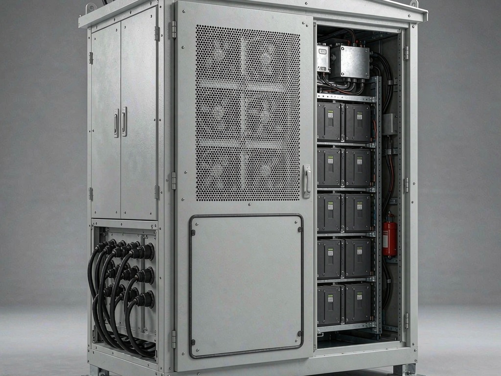
A battery energy storage enclosure is the last component most programs design and the first one the fire marshal asks about. We have built BESS shells for European C&I cabinets, US outdoor skids and containerised units since 2019. On most of those programs the electrical architecture was frozen long before anyone decided where the gas goes. Then a thermal event happens, and the box becomes either a controlled exhaust path or a pressure vessel. This article stays on the metal: what to vent, where to put the barrier, which seams leak first. Where we quote a code requirement we name the clause, and where the answer depends on your cell data we say so rather than filling the gap with a rule of thumb.
Key takeaways
- A lithium-ion cell in thermal runaway releases intense heat, flammable and toxic gases, ejecta and flame. The enclosure needs an engineered gas and pressure strategy that controls pressure, discharge direction and propagation without letting the shell become the release mechanism.
- Three constraints shape every BESS enclosure: pressure (do not let it build), direction (do not point the plume at people, busbars or the neighbouring unit) and delay (slow propagation long enough for detection and response).
- Ingress protection and emergency gas control are separate requirements. An IP66 cabinet still needs an engineered pressure and gas-control strategy — tested relief, emergency ventilation, explosion prevention or a tested combination — without giving up normal-operation sealing.
- UL 9540A is a test method, not a pass/fail certification. Under the 6th Edition, published 13 March 2026, cell and module testing lead to the installation-level large-scale fire test, and the unit-level test is no longer required for non-residential BESS. Acceptance still rests with the adopted code and the authority having jurisdiction.
- The three sheet metal details that decide whether a design survives review are seam continuity, penetration count and the temperature rating of every elastomer in the plume path.
- Ask for the cell-level gas data before you size anything. Every vent calculation is only as good as the gas generation figure behind it.
What actually happens inside a battery energy storage enclosure
The word "fire" misleads people. By the time there is visible flame outside a battery energy storage enclosure, the engineering argument is over. What happens first is a pressure and gas problem, and that is the part the sheet metal controls.
The cascade, in four stages
A cell that has been abused — electrically, mechanically or thermally — enters a self-heating state. The sequence most test houses describe runs broadly like this:
- Onset. Internal shorts form as the separator breaks down. Heat generation exceeds the cell's ability to shed it. The temperature band where this starts depends on chemistry and on how the cell was abused; it is not a fixed number you can design to.
- Gas generation. The electrolyte decomposes and the cell's vent opens. The gas leaving the cell is hot, flammable and toxic — carbon monoxide, hydrogen, methane and ethylene are commonly reported, along with hydrogen fluoride from the salt decomposition.
- Propagation. If the neighbouring cell absorbs enough heat, it vents in turn. This is where enclosure design has the most leverage, because propagation travels by conduction through structure, by radiation across gaps, and by hot gas moving through whatever path the shell offers it.
- Full event. The module or unit is consumed. At full event the question is usually not whether the fire is extinguished — it usually is not — but whether it stays inside, leaves through the intended path, and does not reach the next unit. Those are the three outcomes you can influence from a drawing, and they are worth putting in writing before the first article rather than discovering at test.
Published onset temperatures vary with chemistry and with how the test triggered runaway — nail penetration and external heating produce different numbers on the same cell. Use them to understand the order of events, not to set a set point. The one figure you should take from the cell maker rather than from a table in an article is the peak gas generation rate per cell.
Why the gas changes the design
Three properties of vent gas matter more than flame:
- Volume. A cell produces gas roughly in proportion to its capacity, and it produces it in seconds, not minutes. The enclosure has to pass that flow without the internal pressure climbing into the range where the door, the roof or a seam becomes the release mechanism.
- Temperature. The plume arrives at the vent at temperatures that destroy most polymer parts. Any gasket, cable tie, wire insulation, fan blade or plastic breather in the path is a consumable unless it is specified for it.
- Chemistry. Hydrogen fluoride in the vent gas is corrosive and, in combination with humidity, aggressive towards galvanised surfaces, aluminium and unprotected steel. A unit that survives the event can still fail its corrosion audit six months later. We cover the mechanism in our guide to galvanic corrosion between dissimilar metals.
Three constraints that decide the geometry
Every decision on a BESS enclosure can be traced back to one of three constraints. When a review stalls, it is usually because two of them are being traded without anyone saying so.
| Constraint | What it asks of the shell | How it is verified | Common failure |
|---|---|---|---|
| Pressure | Open a designed path before pressure reaches the weakest structural element | Pressure rise recorded during unit-level testing; comparison against the shell's own limit | Door latch or roof seam releases first, turning the opening into shrapnel |
| Direction | Route the plume away from people, live parts and adjacent units | Observation during testing; radiant heat measured at defined boundaries | Vent pointed at the neighbouring unit or at the DC busbar compartment |
| Delay | Slow cell-to-cell and module-to-module propagation | Temperature at defined monitoring points over a defined period | Barrier omitted because "the BMS will catch it" |
Pressure gets skipped, because the enclosure looks strong. A sealed IP66 cabinet usually holds — right up to the point where the door latch line becomes the release mechanism, and it opens at the fastener rather than through the plate.
Direction gets discovered late. It surfaces during testing, when somebody photographs the plume going somewhere the drawing never intended.
Delay is the constraint procurement tries to delete. Barriers cost money, weigh something and do not appear on a datasheet. The argument we lose most often is "the BMS will catch it" — a detection answer to a propagation question.
Venting architecture: what to put in the wall
Three devices cover most of what gets installed — a burst disc, a reclosing relief valve, or a designed duct path — and cabinets that combine two of them are common. The table below is what we have quoted and built.
| Device | How it works | Strengths | Limits | Typical fit |
|---|---|---|---|---|
| Burst disc / rupture membrane | Opens once at a set differential pressure | Zero power, zero moving parts, full opening in milliseconds, seals tightly until it opens | Single use; must be replaced after an event; activation pressure drifts with temperature and age | Small sealed packs, units where service after an event means replacement anyway |
| Reclosing pressure-relief valve | Spring or weight loaded; reseats after the event | Reusable, testable, can be specified with a defined set pressure | Can be fouled by ejecta; lower flow area than a disc of the same footprint; needs a clear path behind it | Stationary storage, units that are expected to be inspected and returned to service |
| Engineered vent path / duct | A designed channel with a defined cross-section, often with a flame arrester or deflector | Handles high flow, gives you directional control, no single point of failure | Needs space inside the cabinet; must be kept clear of cabling and of stored material; adds a penetration to seal | Containerised and walk-in units, high-energy cabinets |
Sizing: what to actually compute
Vent sizing cannot be reduced safely to one universal equation. The relation below is a screening model for low-pressure, non-choked flow; final sizing has to account for transient gas generation, gas temperature and composition, discharge-path losses, device performance, deflagration loads where applicable, and the test path you are adopting:
Q = C · A · √(2 ΔP / ρ)
where Q is the volumetric flow the vent has to pass, C is a discharge coefficient for the geometry, A is the effective vent area, ΔP is the allowable pressure differential across the shell, and ρ is the density of the gas at the temperature it actually leaves at.
Everything that goes wrong in vent sizing goes wrong in the inputs, not in the formula:
- Q comes from cell data. Peak gas generation rate per cell, the number of cells that can plausibly vent together, and a duration. If you do not have the cell-level gas data, you do not have Q. Rules of thumb expressed as "square centimetres per kilowatt-hour" circulate widely and are not a substitute for the cell manufacturer's measured values.
- ΔP comes from your own shell. The allowable differential is set by the weakest structural element in the assembly — the door latch pitch, the roof seam, the fastener spacing — not by the plate thickness. Know that number before you choose a device.
- ρ is at temperature. Gas density drops sharply with temperature, so using ambient density understates the area required.
- C is measured, not assumed. A deflector, a mesh, a bend or a shroud in front of the vent changes it. If the path is not straight, treat the coefficient as unknown until it is tested.
If a supplier quotes you a vent area without asking for the cell gas data, the number is decoration.
Where should thermal runaway vents be placed?
Place the vent at the top of the affected compartment, or duct the gas there, and route the discharge away from doors, cable entries, DC busbars, walkways and adjacent units. The internal path has to stay clear through installation and service. The rules we hold to:
- Put the vent path at the top of the compartment where the gas goes naturally, or duct it there.
- Keep the outlet clear of the door the technician will open, of the cable entry face, and of the DC compartment.
- Never discharge towards the adjacent unit in a row; a row of cabinets venting into each other is a propagation path, not an exhaust.
- Give the outlet a deflector or shroud if the plume can reach a walkway.
- Keep the internal path clear. A vent behind a cable bundle is a vent that does not exist.
- Do not share the vent path with the cooling airflow unless the design intends it; see enclosure ventilation and thermal management for the normal-operation side of the same cabinet.
Compartmentalisation: buying the delay
Venting deals with pressure. Barriers deal with propagation, and they are usually the difference between a unit-level event and a site-level one.
| Barrier approach | Mechanism | What it does well | What to watch |
|---|---|---|---|
| Air gap plus steel divider | Interrupts conduction and radiation, adds thermal mass | Cheap, structural, doubles as a mounting surface | Radiant transfer across the gap still drives propagation; gap must be real, not nominal |
| Mica or ceramic board | Low thermal conductivity, survives direct flame | Thin, stable at plume temperature, easy to cut and fit | Brittle; needs mechanical retention that survives vibration and shock qualification |
| Intumescent layer | Expands under heat, closes gaps | Seals penetrations and irregular geometry | Single use; expansion needs room to happen |
| Phase-change material | Absorbs heat in the latent transition | Flattens the temperature peak next to the failing cell | Adds mass; needs containment and a defined end-of-life path |
| Mineral wool / ceramic fibre blanket | Insulation with low mass | Conforms to odd shapes, cheap per square metre | Settles and compacts under vibration; needs a facing to stay in place |
Two practical notes from building these. First, the barrier is only as good as the penetrations through it: a busbar slot, a harness pass-through or a mounting bracket that bridges the barrier turns it into a heat path. Second, the barrier has to be retained mechanically, not just bonded — after a vent event the compartment sees pressure from both sides.
The structural form of the cabinet matters here. A welded shell gives you continuous compartments with fewer leak paths; a bolted frame lets you replace a barrier after an event. We worked through that trade-off in welded vs modular enclosure construction, and BESS units sit at the uncomfortable end of it because you want both.
What do UL 9540A and NFPA 855 require of the enclosure?
UL 9540A defines the test method used to characterise thermal runaway fire and explosion behaviour. NFPA 855 governs installation conditions such as spacing and protection. Neither one approves a sheet metal shell on its own. These documents do different jobs, and the split matters at quotation stage, because the enclosure maker's obligations are not the integrator's — getting that boundary wrong is how a supplier ends up promising a listing it cannot deliver.
| Document | What it governs | What it means for the shell |
|---|---|---|
| UL 9540 | System-level product safety listing for the ESS | The enclosure is evaluated as part of the system, not on its own; geometry, materials and clearances have to match what was listed |
| UL 9540A | Test method for evaluating thermal runaway fire propagation. Under the 6th Edition (published 13 March 2026) cell and module testing lead to the installation-level large-scale fire test; unit-level testing is retained for residential BESS and for some non-residential systems with active propagation prevention | It reports observed behaviour and data rather than issuing a universal pass/fail verdict; the adopted code and the AHJ decide acceptance |
| NFPA 855 | Installation of stationary ESS: siting, spacing, fire protection | Sets the default separation between units and the conditions under which that separation can be reduced on the basis of testing |
| NFPA 68 | Deflagration venting | Relevant where a deflagration study is required; it is based on the local gas concentration at the point of cell venting |
| NFPA 69 | Explosion prevention by concentration control | The concentration-reduction route: keep flammable gas below a defined fraction of the lower flammable limit, typically by emergency ventilation |
| IEC 62619 | Safety of secondary lithium cells and batteries for industrial applications | Cell and battery level, including what the BMS must do on detection; sets the electrical response the enclosure has to accommodate |
Four points worth stating precisely, because they are the ones that get garbled:
- Use the edition your project adopts. UL 9540A 6th Edition was published on 13 March 2026. The most significant change is that Section 10 now carries a clear large-scale fire test method aligned with NFPA 855, and the unit-level test is no longer required for non-residential BESS — cell and module testing lead straight to the installation-level test. Unit-level testing remains required for residential BESS and may be used for non-residential systems that rely on active propagation prevention. Ask which edition a report was run to before you rely on it.
- UL 9540A is a method, not a verdict. Whether the result is acceptable is decided by the code, the listing and the authority having jurisdiction. A report that shows no propagation is still just a report.
- NFPA 855 sets a default unit-to-unit separation. The baseline figure is 3 ft (914 mm) between individual ESS units, with a reduction permitted only where fire and explosion testing conducted in accordance with UL 9540A or an equivalent method documents that the smaller distance is adequate and the AHJ accepts it. Note that 3 ft is unit-to-unit only: the spacing matrix also covers property lines, buildings, doors and means of egress, and those distances are larger. Do not hand 3 ft to your contractor as a site layout dimension. Read the edition your jurisdiction has adopted — this chapter has been amended by tentative interim amendment since 2023.
- Explosion control has to be edition-specific. UL Solutions states that UL 9540A is the only fire and explosion test method referenced in the 2026 edition of NFPA 855, and the 6th Edition of UL 9540A adds Annex C, a large-scale deflagration test for BESS enclosures. Where explosion control is required, have the fire protection engineer and the AHJ decide between concentration control under NFPA 69, deflagration venting under NFPA 68, or another approved path — before the geometry is frozen, not after.
Nothing here substitutes for a licensed fire protection engineer or for the AHJ. We build the shell to the geometry the listing describes and hand over the evidence package that supports it; we do not run UL 9540A testing and we do not issue a listing. For the panel-side certification route on industrial enclosures, see UL 508A and IEC 61439; for flammable and combustible material behaviour, see enclosure fire rating and flammability.
Sheet metal decisions that decide whether you pass
Material and thickness
Plate thickness on a BESS cabinet is rarely set by the fire case. It is set by handling, by rack loading and by the stiffness needed to keep door seals compressed over a ten-year service life — the same reasoning that drives sheet metal material selection on every other enclosure we build. Where the fire case does bite is on the barrier support structure and on the vent opening reinforcement — the vent is a hole in a stressed panel, and the frame around it has to carry what the panel used to carry.
Seams and penetrations
Count them. Every seam, every penetration and every removable panel is a place where pressure will find a path and where smoke will leave before the intended vent opens. In practice the leak list looks like this:
- Door perimeter, including the corners where gasket compression is lowest
- Cable entry plates and gland plates
- Any conduit or busbar pass-through between compartments
- Roof seams and lifting points
- Filter and fan apertures on the cooling path
- The vent device's own mounting flange
We go into the sealing mechanics in enclosure gasket sealing to IP65. The BESS-specific point is that sealing has to be reconciled with venting on the same drawing, by the same person, before the panel is cut.
Elastomers in the plume path
The default EPDM or silicone gasket on a door is not specified for a thermal event, and it does not need to be — unless it is in the exhaust path. Anything in the path needs a temperature rating that matches the plume, and anything that has to keep sealing after the event needs to be placed out of it. On the BESS enquiries we have quoted over the last three years this is the line item most often missing from the customer's own drawing note — usually because the drawing says "gasket, EPDM" with no temperature and nobody has crossed the seal list against the exhaust path.
What happens after the event
Vent gas residue plus humidity is a corrosion system. Specify the post-event condition explicitly: which surfaces are sacrificial, which are coated for it, and whether the barrier compartment is designed to be stripped and rebuilt. Coastal and industrial sites compound it. If the unit is also a condensation-managed design, read condensation control alongside this; the two requirements interact at the same drain and breather details.
DFM checklist for a BESS enclosure
- Cell-level gas data available before vent sizing starts
- Allowable internal pressure differential established from the weakest joint, not from plate thickness
- Vent device selected with a stated set pressure and a stated flow coefficient, verified against the enclosure qualification test plan
- Vent path drawn, with clear volume kept free of cabling and hardware
- Discharge direction checked against walkways, adjacent units and the DC compartment
- Barrier material specified with a temperature rating, not just a thickness
- Barrier penetrations enumerated and each one detailed
- Barrier retained mechanically against pressure from both sides
- Gasket temperature rating stated for every seal in the exhaust path
- Total penetration and seam count listed, with each one's sealing method
- Weld sequence and distortion control agreed before the first article — see weld distortion control
- Lifting and transport loads reconciled with the added mass of barriers — see lifting eyes and mounting brackets
- Post-event corrosion condition specified in the coating schedule
- Documentation package listed: material certificates and heat traceability, weld records, coating records and a dimensional report
Three projects, three different answers
A 200 kWh C&I cabinet for a German integrator. The cell supplier had complete cell and module data and the unit was going indoors in a dedicated room. The geometry that came out of it was a welded shell with a single compartment, a reclosing relief valve at the top of the battery compartment, and a deflector turning the plume upward into a ducted path. The barrier was an air gap plus a mica-faced steel divider between module stacks. The thing that took three iterations was not the vent, it was the door. At the differential the client specified, the corner gasket lost the leak check first: a soapy-water test showed beads at the two lower corners and nothing along the straight runs. The fix was to close the latch pitch at the corners. We did not change gasket section, and a larger section would not have closed it.
An outdoor skid for a US utility pilot. Row installation, so direction dominated: the units sit close together, and venting sideways was never on the table. The design moved the outlet to the roof with a shroud, raised the barrier specification to survive direct plume contact, and accepted a heavier, more expensive compartment structure. The client also asked for the exhaust path to be inspectable without opening the battery compartment, which drove a bolted access panel in a welded shell — the hybrid answer we describe in welded vs modular construction.
A containerised unit where the enclosure was not the constraint. On the container jobs, the shell is a structural frame and the fire argument is mostly about spacing, detection and the site plan. Our scope narrows to penetrations, barrier supports and the interface between the container wall and the internal compartments. It is worth saying out loud: on some projects the right answer for the sheet metal supplier is to do less and document it better.
What to put in the RFQ
Paste these fields into your enquiry. You will not get an identical scope back from every shop, but you will get quotations you can lay side by side — which is the actual purpose of an RFQ block. The full field list is in our sheet metal RFQ checklist.
`` Application: stationary BESS cabinet / skid — indoor / outdoor Rated energy per unit: ____ kWh Cell chemistry and cell-level gas data: attached / to be provided by ____ Intended listing path: UL 9540 / IEC 62619 / other ____ Assumed code edition and AHJ: ____ Vent device preference: burst disc / reclosing valve / engineered path / open Allowable internal pressure differential: ____ Pa (or "to be proposed") Barrier material preference and rating: ____ Penetrations to be provided: ____ (list) Gasket temperature rating required in exhaust path: ____ °C Post-event corrosion condition: ____ Documentation required with shipment: ____ Target annual volume: ____ ``
Where to go next
If you are at the enclosure stage of a BESS program, start with energy storage cabinet enclosure design for the general platform, enclosure fire rating and flammability for material behaviour, and UL 508A / IEC 61439 for the panel-side certification path. If you are still choosing the structural route, welded vs modular construction is the decision that everything else hangs off.
Frequently Asked Questions
Does an IP66 battery enclosure need a vent?
Not necessarily a passive vent, but every design needs an engineered pressure and gas-control strategy validated for the adopted code path. An IP66 rating addresses ingress only; it does not prove a safe response to cell venting. The solution may use pressure relief, emergency ventilation, explosion prevention, or a tested combination accepted by the AHJ.
Is UL 9540A a pass or fail test?
It is a test method, not a universal pass/fail certification. Under the 6th Edition, published 13 March 2026, cell and module testing lead to the installation-level large-scale fire test, while unit-level testing remains applicable to residential BESS and certain non-residential cases. Acceptance is determined by the listing, the adopted code and the authority having jurisdiction.
What separation distance does NFPA 855 require between ESS units?
The baseline is 3 ft (914 mm) between individual ESS units, with reductions possible where the required fire and explosion test evidence supports the smaller distance and the AHJ accepts it. That 3 ft is unit-to-unit only and does not cover property lines, buildings or means of egress. Always apply the edition adopted in the project jurisdiction and document the test basis for any reduction.
What is the difference between a burst disc and a reclosing relief valve for a BESS cabinet?
A burst disc opens once at a set differential pressure, gives a large full opening and must be replaced after an event. A reclosing valve reseats after the pressure drops, is testable and reusable, but has less flow area for the same footprint and can be fouled by ejecta. Stationary units that are inspected and returned to service usually specify the valve; sealed units that are replaced after an event often specify the disc.
Can sheet metal alone stop thermal runaway propagation?
Not on its own. A steel divider with an air gap slows conduction and interrupts radiation, but radiant transfer across the gap and any penetration that bridges the barrier still carry heat. Barriers buy time; they are one layer alongside detection, BMS action and spacing.
What documentation should ship with a BESS enclosure?
At minimum, require material certificates with heat traceability, weld records, coating records, a dimensional report on the barrier supports and vent openings, and gasket specifications with temperature ratings. Ask for the complete evidence list at RFQ stage, not at shipment.