"Reduce cost by 30%" is a claim we get asked to justify on almost every RFQ. Sometimes we can, sometimes we cannot — and the difference is almost never the material price. It is the process plan that the drawing forces us to run. This article breaks a custom enclosure quote into the five places cost actually accumulates, and shows which drawing decisions move each one.
Key takeaways
- Material is only one line of the quote. Machine time, setup, welding labour, finishing and scrap usually decide the unit price.
- Nesting yield is the cheapest saving available: it needs no redesign, only flat-pattern discipline and standard sheet sizes.
- One bend radius across the whole part removes tool changes; a different radius per feature adds a setup to every part.
- Weld length is the most expensive millimetre in the drawing — folded and hemmed geometry usually beats a welded corner.
- Tolerance should be allocated to mounting holes, mating faces and sealing surfaces, and nowhere else.
- Sanjun runs free DFM review and free CAD support on every submission, MOQ 1 piece, first articles in 7–15 working days.
The quote has five lines, and material is only one of them
When an enclosure comes back more expensive than expected, the instinct is to renegotiate the steel. In our experience that is rarely where the money is. A sheet metal unit price is built from five accumulators, and each one responds to a different drawing decision:
| Cost accumulator | What inflates it | The DFM lever | Where the saving appears |
|---|---|---|---|
| Raw material | Flat patterns that do not tile onto standard stock; remnant scrap that cannot be reused | Nesting-aware flat patterns, standard sheet sizes, shared nests across part numbers | Lower material issue per part, less remnant write-off |
| Machine time | Long laser pierce counts, single-hit punching, many small features | Cluster tooling, unified hole library, shared bend radius | Fewer pierces and fewer strokes per part |
| Setup and tool changes | A different radius or tool per feature; multiple orientations | Standardise radii, hole sizes and bend directions | Setup minutes disappear from every single part |
| Welding and finishing | Full continuous seams, heavy grinding, rework after distortion | Folded corners, hems, tab-and-slot self-location, PEM hardware | Weld length and post-weld grinding both drop |
| Inspection and scrap | Aerospace-grade tolerances on non-functional dimensions | Functional tolerance allocation, realistic hole-to-bend margins | Higher first-pass yield, shorter inspection cycle |
The 30% figure is real on drawings that arrived over-specified, and unreachable on drawings that were already lean. We would rather tell you which case you are in than quote a number that applies to neither. Our custom sheet metal enclosure cost guide walks through the same five lines from the buyer's side of the table.
Nesting: the saving that needs no redesign
Nesting is how flat patterns are laid out on a sheet before cutting. It is the one lever that changes nothing about the product — the part is geometrically identical afterwards — yet it decides how much of every sheet ends up as scrap. Three things consistently improve it:
- Design to stock sizes. A flat pattern a few millimetres too large can drop a part from two-per-sheet to one-per-sheet. Aligning envelope dimensions with commercially available sheet formats protects yield before nesting software ever runs.
- Share the nest across part numbers. Small brackets and panels from one programme often tile into each other's offcuts. We nest by programme, not by line item, whenever the delivery schedule allows.
- Respect grain direction only where it matters. Bends parallel to the roll direction are more crack-prone on some alloys, but forcing grain alignment on every feature fragments the nest. Reserve the constraint for bends that actually carry load or sit on a visible face.
We report the measured yield on your actual nest rather than quoting a generic percentage, because the number depends entirely on the part mix. The mechanism and the trade-offs are set out in our sheet metal nesting and material yield guide.
One bend radius per part, and flanges long enough to form
A press brake is only productive while it is bending. Every tool change is setup time that gets charged whether or not the part needed it. Specifying a different radius on each feature — a common habit when a CAD model is built feature by feature rather than around a tooling plan — means the operator swaps punches and dies mid-part, and repeats that swap on every unit of the run.
The fix is dull and effective: pick one inside radius that matches a standard punch-and-die set already on the shelf, and hold it across the whole part. Two supporting rules come with it:
- Keep the radius consistent with material behaviour — a tight radius on a high-strength or work-hardening alloy invites cracking along the bend.
- Keep flanges long enough to be formed repeatably. As a working minimum we use 10 mm, which gives the sheet enough contact with the die to locate reliably.
Our sheet metal DFM design guide lists the full rule set, and the bending guide covers springback and the compensation we apply per material.
Weld length is the most expensive millimetre in the drawing
Welding is skilled, manual, and rarely a single operation: a seam implies fit-up, tacking, welding, grinding, and often straightening afterwards. It is also the operation most likely to distort a part that was flat five minutes earlier. On enclosure work, most weld length is removable without weakening anything:
- Fold the corner instead of joining it. A wrapped corner with a hem or a riveted seam carries enclosure loads fine and removes most of the seam.
- Use tab-and-slot self-location. Tabs that key panels together before welding cut fit-up time and hold alignment while the joint is made.
- Replace welded nuts with self-clinching hardware. PEM-style inserts press in during punching and remove a weld, a nut, and a masking step each.
Where a sealed seam is genuinely required — outdoor cabinets targeting IP54 to IP66 — the answer is not to over-weld everywhere, but to put continuous seam only where the ingress path is, and let folded joints carry the rest. See our hem, bend relief and corner joint guide and the weld distortion control guide for how we hold flatness when welding is unavoidable.
Put tolerance where function needs it, and nowhere else
Tolerance is the most expensive thing to give away for free, because it is usually applied by default rather than by decision. A title-block general tolerance class exists precisely so that non-functional dimensions do not need individual values. When a drawing instead applies a tight band across every dimension, three costs appear: extra setup to hold it, inspection time to verify it, and scrap when a capable process still misses it.
Our allocation rule is simple. Tight values go to mounting hole patterns, mating faces and any surface in the sealing path, because fit and ingress protection genuinely depend on them. Everything else falls under the general tolerance class stated on the drawing — for linear and angular dimensions that is the ISO 2768-1 class you nominate, with geometrical tolerancing covered by the general specification you reference rather than by per-feature callouts.
Two geometry rules prevent most tolerance-driven scrap. Keep at least 2–3× sheet thickness between a hole edge and a bend line, or the hole distorts during forming. And keep the hole library small: every additional diameter is another tool station and another setup. The full reasoning is in our sheet metal tolerance guide.
A worked example: four changes on one control cabinet
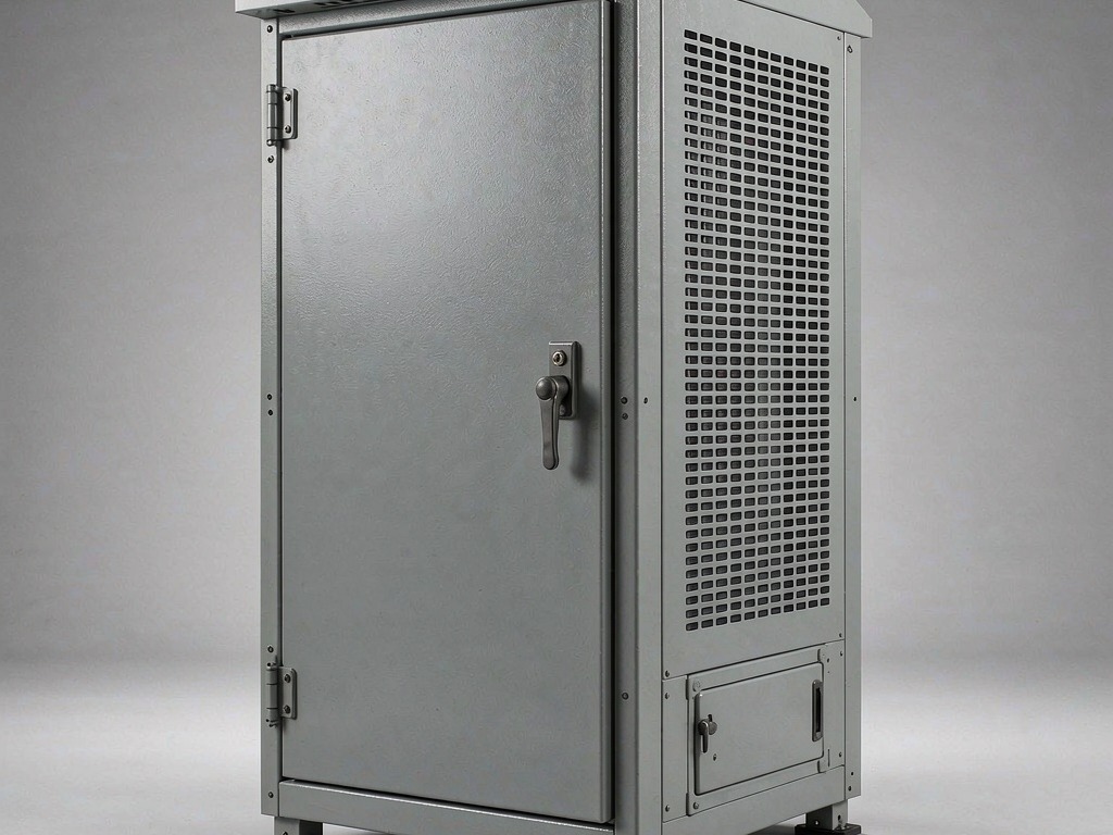
Below is a representative review — not a quotation — of an industrial control cabinet that came to us over-specified. The enclosure function was unchanged in every case; only the process plan moved.
| Item | As submitted | After DFM review | Cost accumulator affected |
|---|---|---|---|
| Bend radii | Three different radii across the chassis | One radius matched to a standard tool set | Setup / tool changes |
| Corner joints | Four continuous welded corner seams | Folded corners with hemmed seams; continuous weld only at the door opening | Welding and finishing |
| Tolerance block | Tight band applied to all linear dimensions | Tight values on mounting pattern and door seal face; general class elsewhere | Inspection and scrap |
| Fasteners | Welded nuts at 16 internal locations | Self-clinching inserts pressed during punching | Welding, assembly labour |
| Flat pattern | Envelope 6 mm over standard stock | Envelope pulled inside standard sheet format | Raw material |
Every one of those is a drawing edit, not a product change. That is why timing matters more than cleverness: the same four items, raised after tooling, become new tools, new fixtures and another first-article cycle. The wider process context is in our sheet metal process and DFM hub.
What to send for a cost review
A useful review needs less than most buyers expect. Send the 3D model or STEP file, the annual volume and the target market, and tell us which dimensions are truly functional — that last item is the one that unlocks most of the saving. Our checklist of what else to include is in the sheet metal RFQ checklist.
We run nine in-house processes from cutting through finishing and box-build assembly in a 5,000 m² plant with a team of over 40, certified to ISO 9001 and ISO 14001 and supplying RoHS and REACH compliant builds. Enclosures are delivered across the IP54 to IP66 range, MOQ is 1 piece, standard lead time is 7–15 working days and custom programmes run 20–30 days. We do not issue CE or UKCA declarations; where a market requires them, that assessment belongs to the finished equipment, and we supply the enclosure evidence to support your own file.
Frequently Asked Questions
Which drawing changes reduce sheet metal cost the fastest?
Standardising bend radii, relaxing tolerances on non-functional dimensions, and replacing welded corner joints with folded or hemmed geometry. These three change the process plan rather than the product function, so they can be applied without a redesign.
Does a cheaper material always lower the total part cost?
No. A lower material price can be cancelled out by extra finishing operations, thicker gauges needed for stiffness, or a higher scrap rate. Total cost is the sum of material, machine time, labour, finishing and scrap, so the material line has to be evaluated together with the process plan.
How much tolerance is reasonable on a custom enclosure?
Tight tolerances belong on mounting hole patterns, mating faces and sealing surfaces, where fit and ingress protection depend on them. Everything else should fall under the general tolerance class stated on the drawing title block, because every tightened dimension adds setup, inspection and scrap.
When should a DFM review happen on a new enclosure programme?
During the 3D CAD stage, before prototypes are built or tooling is committed. Changes made at that point are drawing edits; the same changes made after tooling are new tools, new fixtures and a new first-article cycle.
Conclusion
A 30% reduction is not a discount and not a material swap. It is what happens when the drawing stops asking for operations the product never needed. Send us the model before you freeze it, and we will tell you which of the five accumulators your design is actually loading — including the cases where there is very little left to take out.