A sheet metal enclosure is never really finished until somebody has welded it. Punching, bending and finishing get you individual panels — what turns those panels into a cabinet that holds shape, holds an IP rating, and survives ten years on a charging-station plinth is a string of weld beads laid down with the right process, the right parameters, and the right sequence. Get those three right and the part comes off the table flat. Get them wrong and the doors don't close. This guide walks through the four welding processes a custom enclosure actually sees — MIG, TIG, spot and laser — and how to choose between them, parameterise them, and stop them from warping your parts.
Why Welding Matters in Sheet Metal Fabrication
Modern sheet metal fabrication is a series of cold steps — laser cutting, turret punching, rolling, bending. They deform metal at room temperature and leave it predictable. Welding is the only step that adds energy on purpose. A MIG arc at 90 A is pumping roughly 1.5 kW of heat into a 1.5 mm panel; even a small TIG bead at 40 A delivers several hundred watts into a footprint the size of a coin. That heat is what fuses the joint, but it is also what warps the panel around it. Sheet metal welding is therefore the discipline of putting enough heat in to make the weld — and not one joule more.
The thin-gauge world makes this harder. A 1.2 mm panel has roughly the thermal mass of a sheet of paper per square centimet. It conducts heat fast, so the heat-affected zone spreads. It has very little stiffness, so when the weld bead cools and contracts it pulls the surrounding sheet with it. The result is the classic welded-enclosure failure: a door cutout that was square on the drawing is now a parallelogram, and a base that sat flat on the table is dished in the middle. That is welding distortion, and it is the single most common reason welded sheet metal assemblies are rejected at first-article inspection.
The good news is that distortion is not random — it is a predictable thermal-mechanical response, and it can be controlled. The rest of this guide explains how.
The Four Welding Processes Used in Sheet Metal
MIG (GMAW): The Production Workhorse
MIG — gas metal arc welding, also known as GMAW — uses a continuously fed consumable wire as both the arc electrode and the filler material. The welder just pulls the trigger and moves the gun along the seam. Because the wire feeds automatically, MIG is the fastest of the arc processes and the easiest to learn. Short-circuit transfer mode (low voltage, thin wire) makes MIG viable on steel down to about 0.8 mm; pulse MIG and Cold Metal Transfer (CMT) push that lower limit to around 0.6 mm. On carbon steel above 1.5 mm, MIG is the default process in nearly every sheet metal shop — fast, productive, easy to automate. The trade-off is cosmetic: MIG leaves spatter and a rougher bead, so it is the right choice for frames, brackets and hidden seams, less so for visible faces.
TIG (GTAW): Precision for Thin Stainless and Aluminum
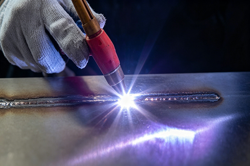
TIG — gas tungsten arc welding, GTAW — uses a non-consumable tungsten electrode and a separate filler rod fed by hand or by a cold-wire feeder. The arc is shielded by argon (or argon-helium mix for aluminum) and the welder modulates it with a foot pedal, which gives precise control of the weld puddle second to none. The trade-off is speed — a skilled TIG welder deposits 0.5–1.5 kg of filler per hour, versus 2–10 kg/h for MIG — and operator skill.
TIG is the standard process for stainless steel under 2 mm, for aluminum of any gauge (TIG on AC current breaks up the oxide layer), for cosmetic seams, and for any weld that will be visible on the finished part. For food-grade, medical and architectural sheet metal, TIG is essentially non-negotiable because the bead can be polished and passivated to a sanitary finish. Pulse TIG reduces average heat input by cycling current between peak and background levels, which is what makes 0.6–1.0 mm sheet practical on stainless without burning through.
Resistance Spot Welding (RSW): Fast Lap Joints
Spot welding passes a high current (typically 4–8 kA for sheet metal) through two copper electrodes clamping two overlapping sheets. The resistance at the faying surface generates enough heat to melt a small nugget of metal and fuse the sheets together in a fraction of a second, with no filler and no shielding gas. The weld nugget diameter follows the rule of thumb D ≈ 5 × √t, where t is the individual sheet thickness in mm; for two 1 mm sheets, that is roughly 5 mm. Electrode tip diameter is sized slightly larger.
Spot welding is the dominant joining process in automotive body-in-white — a single car contains 3,000–5,000 spot welds — and is also widely used for enclosures, cabinets, transformer cases and panels where lap joints are acceptable. Robotic spot welding cells can lay hundreds of spots per hour with consistent nugget size and electrode force, which is exactly the consistency a high-volume OEM needs. Spot welds are not continuous seams, so they cannot seal a fluid or pressure vessel — for that you need stitch or seam welding.
Laser Welding: Minimal Heat Input, High Precision
Laser welding uses a focused laser beam (typically 400–1000 W fibre laser for sheet metal) to fuse the joint in a very narrow, very deep weld pool. The heat-affected zone is tiny — typically a fraction of a millimetre wide — and the total energy per millimetre of weld is well below what an arc process can match. The result is the lowest distortion of any fusion process, which is why laser welding is the standard for thin stainless and aluminum enclosures in electronics, medical devices, battery trays and other tight-tolerance applications. The catch is fit-up: a laser wants a joint gap close to zero, so parts have to nest and clamp precisely before the laser fires. Robotic laser cells integrate seam tracking and gap measurement, but the upstream blank preparation has to be disciplined.
Process Selection: Material × Thickness × Volume
There is no universally best process. The right choice depends on three things: base material, material thickness, and production volume. The table below maps the most common cases. Use it as a starting point, then check the fabricator's WPS (welding procedure specification) for the parameter windows that work on their actual equipment.
| Material / Thickness | Cosmetic Requirement | Volume | Recommended Process | Why |
|---|---|---|---|---|
| Mild steel ≥ 1.5 mm | Hidden / structural | Any | MIG (GMAW) | Fast, productive, easy to automate |
| Mild steel 0.8–1.5 mm | Hidden | Any | MIG short-circuit / pulse | Possible with pulsed or CMT transfer |
| Stainless steel 0.5–2 mm | Visible or sanitary | Any | TIG (GTAW), pulse | Clean bead, low HAZ, no spatter |
| Stainless steel 2–4 mm | Any | Production | MIG (pulsed) or laser | Cosmetic OK if MIG; laser for tight tolerance |
| Aluminum 1–3 mm | Visible | Any | TIG AC | AC balance breaks oxide layer, clean bead |
| Aluminum 3–6 mm | Structural | Production | MIG with spool gun / push-pull | Faster than TIG; avoid standard drive rolls |
| Lap joints 0.5–3 mm overlap | Hidden | High volume | Spot (RSW) or projection | Sub-second cycle, no filler, easy to robotise |
| Tight-tolerance thin stainless / aluminum | Visible | High volume | Laser (fibre) | Minimal distortion, narrow HAZ |
One thing the table cannot capture is the fabricator's equipment and skill. A shop that runs a robotic MIG cell all day will produce a better MIG weld on a BESS cabinet than a hand TIG specialist. A job-shop TIG expert will produce a better visible seam on a 0.8 mm stainless panel than a robotic MIG cell. Ask your supplier what process they actually run most often on similar parts — that single question predicts cosmetic and tolerance outcomes more reliably than any spec sheet.
Starting Parameters: Reference Ranges
Parameter windows below are starting points drawn from common production experience on carbon steel, stainless steel and aluminum sheet. They are not procedure qualifications. Always confirm against the fabricator's WPS, which is qualified for their specific machine, wire and shielding gas.
MIG (GMAW) Starting Parameters — Carbon Steel
| Thickness | Current (A) | Voltage (V) | Wire Ø | Notes |
|---|---|---|---|---|
| 0.8 mm | 40–70 | 16–18 | 0.8 mm | Short-circuit transfer; stitch welds only |
| 1.0 mm | 50–90 | 17–19 | 0.8–0.9 mm | Stitch welding recommended |
| 1.5 mm | 70–110 | 18–20 | 0.9 mm | Pulsed MIG preferred |
| 2.0 mm | 90–130 | 19–22 | 1.0 mm | Stable arc, moderate penetration |
| 3.0 mm | 130–180 | 21–24 | 1.0–1.2 mm | Continuous beads acceptable |
TIG (GTAW) Starting Parameters — Stainless Steel
| Thickness | Current (A) | Tungsten Ø | Filler Ø | Argon Flow | Notes |
|---|---|---|---|---|---|
| 0.8 mm | 20–50 | 1.6 mm | — (autogenous) or 1.0 mm | 8–10 L/min | High operator skill; pulse recommended |
| 1.0 mm | 40–60 | 1.6 mm | 1.0 mm | 8–10 L/min | Use backing gas to prevent oxidation |
| 1.5 mm | 50–80 | 1.6–2.4 mm | 1.0–1.6 mm | 10 L/min | Stable arc, full penetration |
| 2.0 mm | 70–100 | 2.4 mm | 1.6 mm | 10–12 L/min | Argon backing preserves corrosion resistance |
| 3.0 mm | 100–140 | 2.4–3.2 mm | 1.6–2.4 mm | 12–15 L/min | Multi-pass if full penetration required |
Spot Welding (RSW) Starting Parameters — Low-Carbon Steel
| Single Sheet Thickness | Weld Time | Electrode Force | Approx. Current | Min. Pitch |
|---|---|---|---|---|
| 0.5 mm | 0.1–0.2 s | 1.5–2.0 kN | 4–5 kA | ~10 mm |
| 0.8 mm | 0.15–0.25 s | 2.0–2.5 kN | 5–6 kA | ~12 mm |
| 1.0 mm | 0.2–0.3 s | 2.5–3.0 kN | 6–7 kA | ~15 mm |
| 1.5 mm | 0.25–0.4 s | 3.0–4.0 kN | 7–8 kA | ~20 mm |
| 2.0 mm | 0.3–0.5 s | 4.0–5.0 kN | 8–9 kA | ~25 mm |
Distortion Control: How to Prevent Welding Warping
Distortion is the predictable response of thin sheet to a moving line of localised heat. The weld zone expands as it heats, is restrained by the surrounding cold metal, then contracts as it cools and pulls the assembly with it. Every distortion-control technique reduces one of three things: total heat input, time at temperature, or the length of unrestrained metal. The five that pay off most on the shop floor are below. Welded-on hardware is a distortion case of its own: our lifting eye and mounting bracket guide shows the doubler plates and rib collars that keep a lug from pulling the cover out of flat.
1. Stitch rather than run continuous. The single highest-leverage change. Replace a 500 mm continuous fillet weld with stitch welds — say 20 mm weld, 30 mm gap, 20 mm weld — and you cut cumulative heat input by 50–70% while keeping more than enough strength for an enclosure frame. Reserve continuous welds for sealed, structural or pressure-bearing joints; use stitches everywhere else.
2. Balance the weld pattern. Welds on one side pull the panel toward that side. Symmetric, opposed or balanced weld layouts let contraction forces cancel rather than accumulate. A useful shop rule for boxes is: do not complete one whole side before touching the other, or the box may have already chosen its new shape.
3. Sequence from the centre outward. Back-step or skip welding distributes heat and gives the centre of the seam time to cool before you come back. On long seams, weld a short segment, jump to the far end, weld another short segment, jump back — the contraction forces do not have a chance to line up in one direction.
4. Fixture to functional datums. A good jig holds the assembly through cooling on the same datums the drawing dimensions from. Over-clamping looks tidy in the fixture and springs out the moment you release; under-clamping lets the part wander during welding. Copper or brass backing bars double as both a heat sink (pulling thermal energy into the bar so it doesn't soak into the panel) and a chill that keeps the HAZ narrow — invaluable on visible stainless and aluminum cosmetic seams.
5. Design welds out. The cheapest distortion is the weld you never make. A tab-and-slot joint, a hem, a formed return, or a bend that replaces a welded corner removes heat input entirely. Formed corners are also cheaper and faster than welded corners and need no finishing. The rule from our sheet metal design for manufacturability guide applies here as well — wherever bending can replace welding, bend it.
Welding Across SanJun's Six Product Lines
Welding choice is not generic. The same welded enclosure behaves very differently depending on what it has to do. Here is how the four processes map onto our six product lines, with the dominant trade-off in each.
- New energy charging (EV charger enclosures) — typically 1.5–2 mm cold-rolled or stainless steel, IP54–IP65, frequently outdoor. Main trade-off is cosmetic + sealing. Visible faces use TIG; structural seams under the skin use MIG. Weld sequencing and backing-bar use are critical because door and display cutouts are dimensionally tight.
- Energy storage and power (BESS cabinets) — large, heavy-gauge (2–4 mm), many long seams. Robotic MIG or CMT pulse MIG on a rigid fixture is the workhorse. Stitch welding and balanced sequences keep the cabinet square so the modules stack. Stainless cabinets for coastal sites add passivation after welding to recover corrosion resistance in the HAZ.
- Industrial HMI and monitor enclosures — thin (often 1–1.5 mm) front panels with tight cutout tolerances. TIG or laser is the only realistic process for visible front-panel welds; pulsed TIG on aluminum with AC balance gives the cosmetic finish display OEMs expect. The DFM approach in our industrial HMI enclosure design guide complements the welding choice — design the panel so the cosmetic weld sits on a hidden flange where possible.
- Telecom and network enclosures — chassis that often require EMC shielding. EMC depends on tight seam contact and a continuous, oxide-free weld. TIG with argon backing on stainless gives a continuous, low-resistance joint; spot welding is fine for non-shielded structural seams inside the cabinet. For the broader EMC picture, see our telecom and network enclosure guide.
- Industrial control panels — usually 1.5–2 mm cold-rolled steel with a focus on serviceability. MIG for the frame, spot for internal bracketry, stud welding for grounding points and backpanel hardware. Formed corners and bends replace welding wherever they can — control panels get opened repeatedly for service, and welded corners concentrate stress.
- Outdoor security and municipal enclosures — thick stainless or aluminum for corrosion resistance and vandal resistance. TIG or MIG with pulsed transfer; stainless typically needs larger weld preparation, more heat input, and post-weld passivation or powder coating. Our outdoor waterproof enclosure IP guide covers the sealing side; welding is the structural side of the same conversation.
How to Specify Welds on a Drawing
A drawing without weld symbols forces the fabricator to guess. The two standards you will see in practice are AWS A2.4 (North America) and ISO 2553 (Europe and most of Asia). The basic symbols are nearly identical between them; the differences are in how the symbol is laid out around the reference line.
The minimum set every enclosure drawing should call out:
- Weld type — fillet, square-groove, V-groove, spot, plug, etc. (triangle below reference line = arrow-side fillet in AWS; on the solid line in ISO).
- Weld size — leg length for fillet (number to the left of the symbol); throat or depth for grooves.
- Length and pitch — number to the right of the symbol; for intermittent welds, length-pitch format (e.g. 20-50 means 20 mm weld every 50 mm centre-to-centre).
- Process — in the tail, GMAW/GTAW/RSW in AWS or ISO 4063 numeric codes (135, 141, 21) in ISO.
- Supplementary — weld-all-around circle, field-weld flag, contour (flush / convex / concave) plus optional finish letter (G = grind, M = machine, C = chip).
A common callout on an enclosure drawing looks like this: "Fillet weld, 3 mm leg, 20 mm long every 50 mm, GTAW per AWS A2.4, arrow side, intermittent." That one symbol tells the welder the type, the size, the length, the pitch and the process. Adding "field weld" with a flag tells them it happens on site. Adding a contour mark with a "G" tells them to grind it flush.
Two things to leave off drawings unless they matter: weld procedure qualifications beyond what your part requires, and tolerances tighter than what the WPS can actually hold. Both slow the quote and rarely help the part.
Common Defects and How to Avoid Them
| Defect | What it is | Most common cause | Fix |
|---|---|---|---|
| Burn-through | Hole melted through the sheet | Too much heat on thin gauge | Lower current, faster travel, pulse mode, backing bar |
| Lack of fusion | Weld bead sits on the surface without fusing | Too little heat, dirty surface, wrong torch angle | Clean base metal, increase heat, adjust angle |
| Porosity | Gas bubbles trapped in the weld | Contaminated base metal, lost shielding gas (wind), damp electrodes | Clean and degrease, shield from wind, dry storage |
| Cracking | Hot or cold cracks in weld or HAZ | High restraint, wrong filler, high carbon equivalent | Reduce restraint, use low-hydrogen filler, preheat |
| Distortion | Panel warps after welding | Excessive continuous heat input | Stitch welding, balance sequence, fixture, redesign as bend |
| Discoloration on stainless | Heat tint in HAZ | Oxidation during welding | Argon backing, pickling passivation, electropolish |
Shrinkage does not stop at the seam: on a large thin panel it shows up as a pucker along the weld line, which is a flatness problem rather than a weld defect. The mechanics and the fixes are in the oil canning and flatness guide.
Frequently Asked Questions
Which welding process is best for thin stainless steel sheet metal?
TIG (GTAW) is the standard choice for stainless steel under about 2 mm. Use pulsed TIG, DC with argon backing on the reverse side, and run intermittent welds to keep heat input low. For visible seams on food-grade or medical-grade enclosures, TIG is essentially non-negotiable.
How do you stop welded sheet metal from warping?
Use stitch welds instead of continuous beads, alternate weld positions on opposite sides of the assembly, fixture the part on its functional datums and hold it through cooling, and design with formed flanges or tab-and-slot joints so welding is replaced by forming where possible. Reserve continuous welds for sealed, structural or pressure-bearing joints.
What is the difference between MIG and TIG for sheet metal?
MIG (GMAW) uses a continuously fed consumable wire and is fast and easy to automate — the workhorse for steel above about 1 mm in production. TIG (GTAW) uses a non-consumable tungsten electrode with separate filler, is slower, and is the preferred process for cosmetic seams, aluminum and stainless under 2 mm. The two are complementary rather than competing.
What thickness can spot welding join in sheet metal?
Resistance spot welding is practical on overlapping low-carbon or stainless steel pairs from 0.5 mm to 3 mm each. The weld nugget diameter is roughly 5 × √t where t is individual sheet thickness in mm — about 5 mm for two 1 mm sheets. Spot welds cannot seal a fluid or pressure vessel; for that, use stitch or seam welding.
What does a fillet weld symbol with a length-pitch number mean?
In AWS A2.4, a fillet triangle below the reference line means the weld is on the arrow side. The number to the left of the symbol is leg size (e.g. 3 mm); the number to the right is weld length, with optional pitch for intermittent welds. A callout like "20-50" means 20 mm weld every 50 mm centre-to-centre.
Conclusion
Sheet metal welding is a four-process toolbox — MIG, TIG, spot and laser — chosen by material, thickness, cosmetic requirement and volume, parameterised with starting ranges from a WPS, and controlled against distortion with stitch welding, balanced sequencing, fixturing and, where possible, designing the weld out entirely. Master those, and your enclosures come off the table flat, sealed and ready for surface finishing.
Send us your CAD files and drawings — our engineers will run a free weld-process review and return a quotation, with manufacturability notes that often cut fabrication cost by 20–40% before any welding starts.
The cut edge arrives already conditioned by the laser, and the assist gas decides whether it is weld-ready: nitrogen-cut edges generally are, oxygen-cut edges carry an oxide film that should come off first.
A weld can pass every structural check and still be rejected on appearance, so agree what the finished seam is allowed to look like — quality level, prohibited defects, limit sample — before the first arc is struck.
Welding is one of four joining decisions; distortion, appearance and construction method are the other three, and the set is in the sheet metal process cluster.